Upward waste blanking structure

A scrap and blanking technology, which is applied in the field of upward punching out of scrap structures, can solve problems such as low working efficiency of molds, achieve the effects of improving practicability and safety, reducing molding time, and saving operations

Pending Publication Date: 2022-06-03
重庆晋川精密五金有限公司
View PDF1 Cites 0 Cited by
  • Summary
  • Abstract
  • Description
  • Claims
  • Application Information

AI Technical Summary

Problems solved by technology

[0005] For the mold of the prior art, when the upper template is extruding the lower template, there is only a buffering effect, and the rubbish existing on the lower template needs to be cleaned manually during extrusion molding, which in turn causes the working efficiency of the mold to be low Insufficient, the present invention provides a kind of upward punching out waste material structure

Method used


Image

  • Upward waste blanking structure
  • Upward waste blanking structure
  • Upward waste blanking structure

Examples


Embodiment

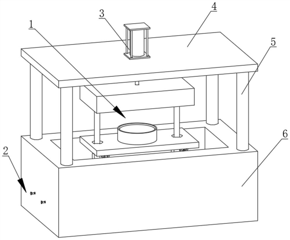
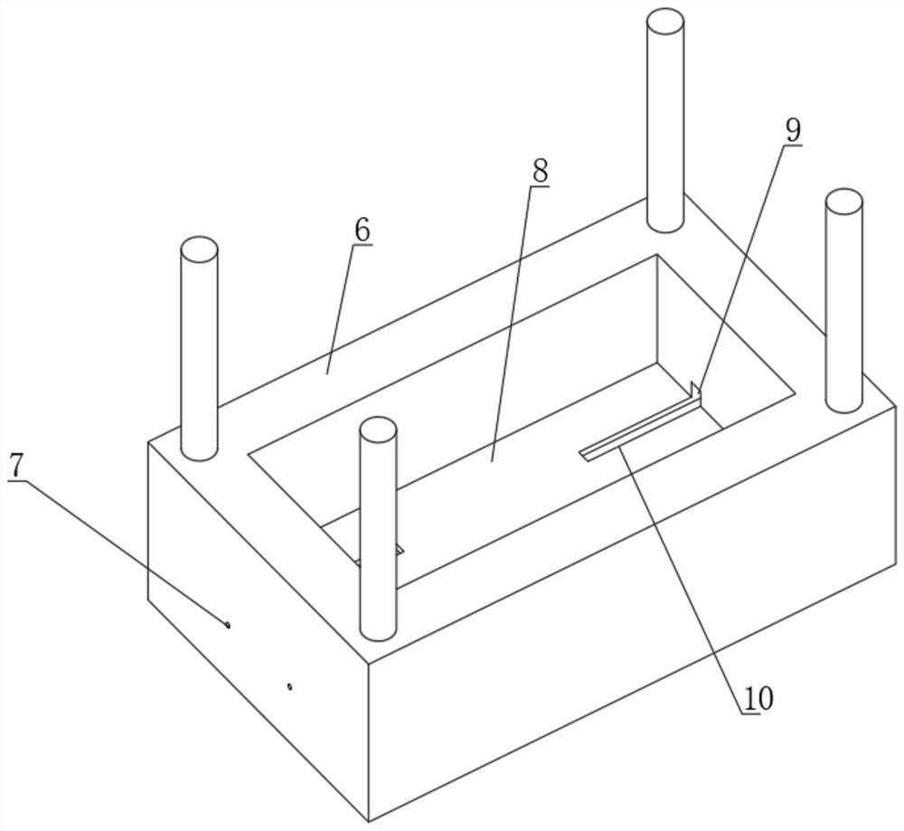
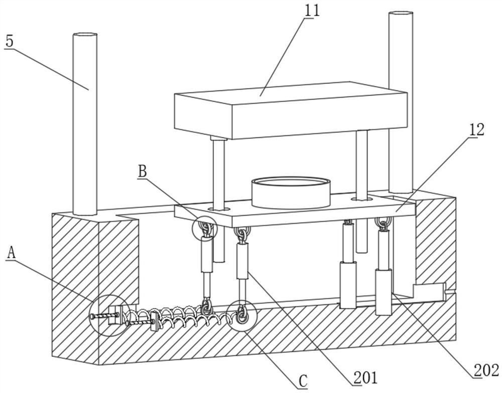
[0032] like Figure 1-9 As shown, an upwardly punched waste structure includes an upper plate 4 and a bottom plate 6, the upper surface of the bottom plate 6 is fixedly connected with the upper plate 4 through four support rods 5, the bottom plate 6 is provided with a collection groove 8, and the collection groove 8 A waste collection assembly 2 is arranged on the upper plate, the waste collection assembly 2 is connected to the lower end of the lower template 12, the upper surface of the upper plate 4 is fixedly connected with a cylinder 3, the output shaft of the cylinder 3 slides through the upper plate 4, and the output shaft end of the cylinder 3 It is fixedly connected to the upper surface of the upper template 11. The upper template 11 and the lower template 12 are provided with a waste cutting assembly 1. Both sides of the lower end of the upper template 11 are provided with movable rods 106. The movable rods 106 cooperate with the limit holes 102. On the top, two limit...


PUM


Abstract

The invention relates to the technical field of dies, in particular to an upward waste blanking structure which comprises an upper plate and a bottom plate, the upper surface of the bottom plate is fixedly connected with the upper plate through four supporting rods, the bottom plate is provided with a collecting groove, the collecting groove is provided with a waste collecting assembly, the waste collecting assembly is connected to the lower end of a lower die plate, and the lower die plate is fixedly connected with the upper plate. An air cylinder is fixedly connected to the upper surface of the upper plate, an output shaft of the air cylinder penetrates through the upper plate in a sliding mode, the end of the output shaft of the air cylinder is fixedly connected to the upper surface of the upper die plate, and waste cutting assemblies are arranged on the upper die plate and the lower die plate. And therefore, waste on the upper surface of the lower die plate obliquely flows into the collecting groove, the effect of automatically collecting the waste is achieved, the operation amount of workers is reduced, meanwhile, the forming time of the die is shortened, and the production rate of equipment is increased.

Description

technical field [0001] The invention relates to the technical field of molds, and in particular, to a structure for punching out scraps upwards. Background technique [0002] Molds, various molds and tools used in industrial production to obtain the desired products by injection molding, blow molding, extrusion, die casting or forging, smelting, stamping and other methods. For example, the patent number is CN202021287523.6, a metal mold tooling includes a metal mold tooling support bottom plate, a support and fixed connecting rod, a metal mold tooling fixed top plate, a hydraulic press, a support limit connecting plate, and a spring. One side is connected to the support and fixed connecting rod, the metal mold tooling support base plate is located on one side of the support and fixed connecting rod, and a limit connecting rod is installed, and the second fixed extrusion block is located on the support limit connecting plate One side of the spring is connected to the spring,...

Claims


Application Information

Patent Timeline
Patent Type & Authority Applications(China)
IPC IPC(8): B21D35/00B21D37/08B21D45/08B21D55/00F16F15/02F16F15/023F16F15/067
CPCB21D35/002B21D37/08B21D45/08B21D55/00F16F15/022F16F15/0232F16F15/067Y02P70/10
Inventor 邓庄坤王朝勇许斌
Owner 重庆晋川精密五金有限公司
Why Eureka
Try Eureka