Side fixing frame for a liquid crystal display device

Active Publication Date: 2005-09-22
AU OPTRONICS CORP
View PDF4 Cites 17 Cited by
  • Summary
  • Abstract
  • Description
  • Claims
  • Application Information

AI Technical Summary

Benefits of technology

[0013] The fastening means of the present side fixing frame is based on the theory of securing with three points. The edge of the side fixing frame can be made narrower; and this can increase the view field of the liquid crystal display device. Therefore, the present invention increases the view field of the liquid crystal display device comparably more than the

Problems solved by technology

Making liquid crystal display devices lighter and slimmer causes the upper frame 100 to be made very soft and results in the difficulty of mold injection.
The assembly also becomes more complicated.
This reduces the view field of the liquid crystal display panel, and increasing the overall size and weight of the backlight module.
However, to attain a good securing effect, the edge of the side mold frame can not be made too narrow; otherwise,

Method used


Image

  • Side fixing frame for a liquid crystal display device
  • Side fixing frame for a liquid crystal display device
  • Side fixing frame for a liquid crystal display device

Examples


Embodiment Construction

[0021] The present invention will be described in detail in accordance with the following embodiments with reference to the accompanying drawings.

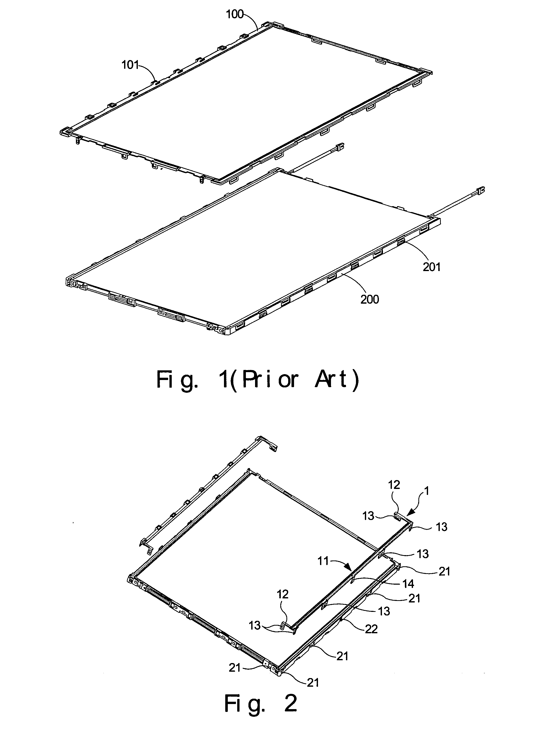
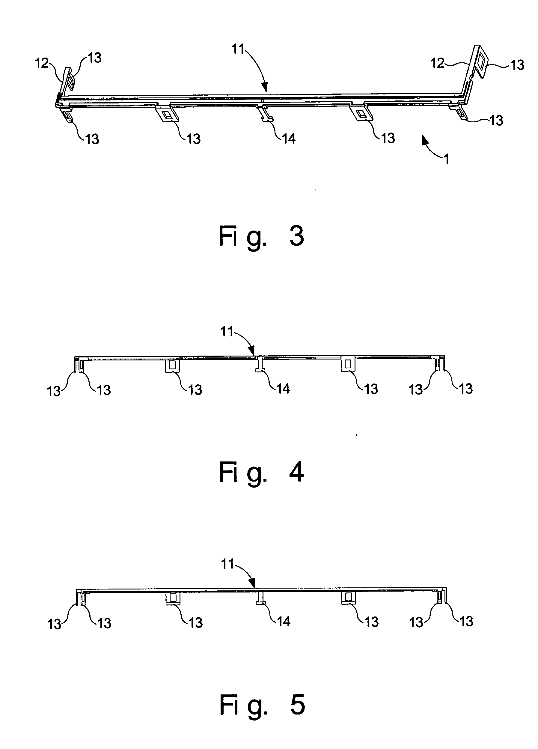
[0022]FIG. 2 is a disassembled perspective view of a supporting frame and two side fixing frames 1 of the present invention. FIG. 3 is a perspective view of the side fixing frame 1 of the present invention. A LCD panel (not shown) is disposed directly contacting the upper side of the side fixing frame 1. The components of the backlight module such as a light guiding plate, a reflecting plate are disposed between the supporting frame and the side fixing frame 1 to form the backlight module of the LCD device. The side fixing frame 1 substantially includes a frame body 11 and a pair of extended parts 12. The frame body 11 and the extended parts 12 form a U-shaped configuration. The frame body 11 is provided with multiple of engaging elements 13 and 14, and one end of each of the extended parts 12 is provided with at least one engaging elemen...


PUM


Abstract

A side fixing frame for a liquid crystal display device is provided. The side fixing frame has a U-shaped configuration and is provided with multiple engaging elements. The engaging elements of the side fixing frame couple with corresponding counterparts of a supporting frame used in a liquid crystal display device so as to fasten the side fixing frame with the supporting frame. Because of the U-shaped configuration design of the side fixing frame, the frame can attain the desired securing strength and reduce the materials needed for producing the side fixing frame and the production cost.

Description

BACKGROUND OF THE INVENTION [0001] 1. Field of the Invention [0002] The present invention relates to a side fixing frame for a liquid crystal display device, and particularly to a U-shaped side fixing frame with multiple engaging elements to couple and to secure a supporting frame of a liquid crystal display device. [0003] 2. Description of the Prior Art [0004] As semiconductor fabrication technologies are rapidly advanced, display devices are required to be lighter, smaller and slimmer. This is especially the true for flat panel display devices such as liquid crystal displays and plasma displays. Therefore, the industry endeavors in reducing the number of assembly elements and in simplifying the process to the greatest extent possible. [0005] LCD monitors are widely used for desktop computers and notebook computers. A LCD panel module and a backlight module are respectively assembled using separate assembly processes before both are assembled together. FIG. 1 is a disassembled pers...

Claims


Application Information

Patent Timeline
IPC IPC(8): G02F1/13G02F1/1333
CPCG02F2001/133322G02F1/133308G02F1/133322
Inventor LI, SZU-HANCHUANG, YUNG-PINLU, LI-HUANGSHIAU, DENG-KUEN
Owner AU OPTRONICS CORP
Why Eureka
Try Eureka