Pushing and flattening device for inlaying arbor wheel of light lifting machine

A technology for cranes and shaft wheels, applied in the field of pushing and flattening devices inlaid with shaft wheels of light cranes, can solve the problems of cumbersome installation and disassembly, unfavorable disassembly and maintenance, and prone to corrosion, etc., and achieves convenient disassembly, simple structure, Effect of preventing damage and deformation

Inactive Publication Date: 2018-08-17
杨静
View PDF0 Cites 0 Cited by
  • Summary
  • Abstract
  • Description
  • Claims
  • Application Information

AI Technical Summary

Problems solved by technology

[0002] The existing pushing and flattening devices used for inlaying shafts and wheels of light-duty cranes have certain defects in design. First of all, the ordinary pushing and flattening devices for inlaying shafts and wheels of light-duty cranes have complex structures. The process of installation and disassembly is relatively cumbersome. When the device fails to work, it is not conducive to timely disassembly and maintenance. Secondly, in order to ensure the stability of the device during flattening, the pushing and flattening device inlaid with the shaft and wheel of the ordinary light-duty crane often adopts a relatively Heavy steel structure push rod, high cost, heavy weight, and prone to rust after long-term use

Method used


Image

  • Pushing and flattening device for inlaying arbor wheel of light lifting machine
  • Pushing and flattening device for inlaying arbor wheel of light lifting machine
  • Pushing and flattening device for inlaying arbor wheel of light lifting machine

Examples


Embodiment Construction

[0018] The preferred embodiments of the present invention will be described in detail below in conjunction with the accompanying drawings, so that the advantages and features of the present invention can be more easily understood by those skilled in the art, so as to define the protection scope of the present invention more clearly.

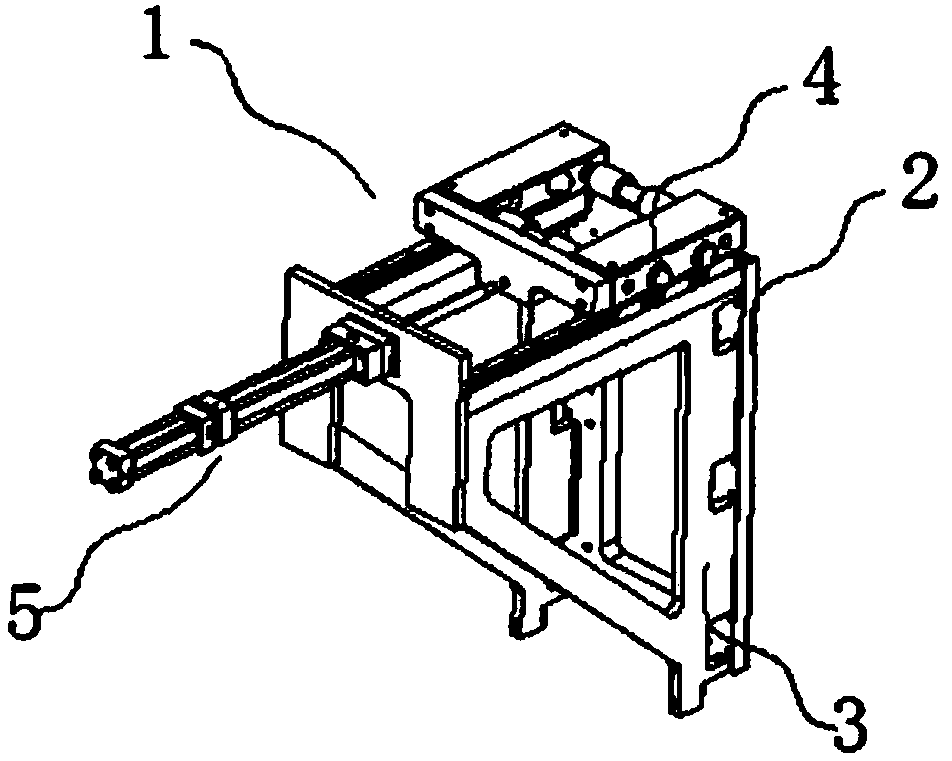
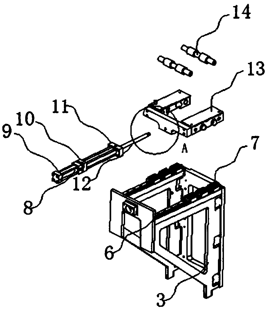
[0019] Such as Figure 1 to Figure 4 As shown, the pushing and flattening device 1 for inlaying the shaft and wheel of a light-duty crane includes a mounting plate 2, a support frame 3 is installed on one side of the mounting plate 2, and a pushing component 4 is installed above the supporting frame 3, and the pushing component 4 A push rod assembly 5 is installed on one side, and several slide rails 6 are arranged on the top of the support frame 3, and several slide blocks 7 are installed on the top of the slide rail 6, and the push rod assembly 5 includes a center rod 8, and the top of the center rod 8 and A connection block 10 is installed in ...


PUM


Abstract

The invention discloses a pushing and flattening device for inlaying an arbor wheel of a light lifting machine. The pushing and flattening device comprises a mounting plate; a supporting frame is installed at one side of the mounting plate; a pushing component is installed above the supporting frame; a push rod component is installed at one side of the push component; a plurality of sliding railsare arranged at the top of the supporting frame; the top of each sliding rail is provided with a plurality of sliders; the push rod component comprises a center rod; and the top end and the middle part of the center rod are each provided with a connecting block. When the pushing and flattening device is used, a user firstly stably installs the pushing and flattening device on a mechanical transmission component by using a mounting plate so that the pushing and flattening device can be conveniently dismounted in later period; the transmission component is used for driving a base block to move horizontally; the base block is used for driving the sliders to smoothly move on the smooth sliding rails; by the effect of a connecting rod matched with a connecting hole which is formed in a push plate, the overall push rod component moves more smoothly; and the center rod is stably fixed by virtue of a plurality of auxiliary rods which surround the center rod so that damages and deformation of the center rod are prevented in a flattening process.

Description

technical field [0001] The invention relates to a pushing and flattening device, more precisely, a pushing and flattening device used for inlaying shaft wheels of light-duty cranes. Background technique [0002] The existing pushing and flattening devices used for inlaying shafts and wheels of light-duty cranes have certain defects in design. First of all, the ordinary pushing and flattening devices for inlaying shafts and wheels of light-duty cranes have complex structures. The process of installation and disassembly is relatively cumbersome. When the device fails to work, it is not conducive to timely disassembly and maintenance. Secondly, the pushing and flattening device inlaid with the shaft wheel of the ordinary light crane is often used to ensure the stability of the device during flattening. Heavy steel push rods are expensive, heavy, and prone to corrosion after long-term use. Contents of the invention [0003] The present invention mainly solves the technical pr...

Claims


Application Information

Patent Timeline
IPC IPC(8): B21D1/00B21D3/00
CPCB21D1/00B21D3/00
Inventor 杨静
Owner 杨静
Why Eureka
Try Eureka