Digital instrument pointer display system and method
What is AI technical title?
AI technical title is built by PatSnap AI team. It summarizes the technical point description of the patent document.
A technology of digital instruments and display systems, applied in the field of digital instruments, to achieve the effects of high visual fluency, guaranteed display fluency, and high real-time response
Inactive Publication Date: 2018-08-17
SHENZHEN HCN ELECTRIC APPLIANCE CO LTD
View PDF8 Cites 5 Cited by
Summary
Abstract
Description
Claims
Application Information
AI Technical Summary
This helps you quickly interpret patents by identifying the three key elements:
Problems solved by technology
Method used
Benefits of technology
Problems solved by technology
[0005] Based on this, it is necessary to provide a digital instrument pointer display system and method for the problems existing in the existing vehicle instrument display, wherein, through the pointer display of the digital instrument dial, which is a key technical point, the accuracy of the digital instrument pointer display is high. , High real-time response, high visual fluency
Method used
Image
Click on the blue label to locate the original text in one second.
Reading with bidirectional positioning of images and text.
Examples
Embodiment 1
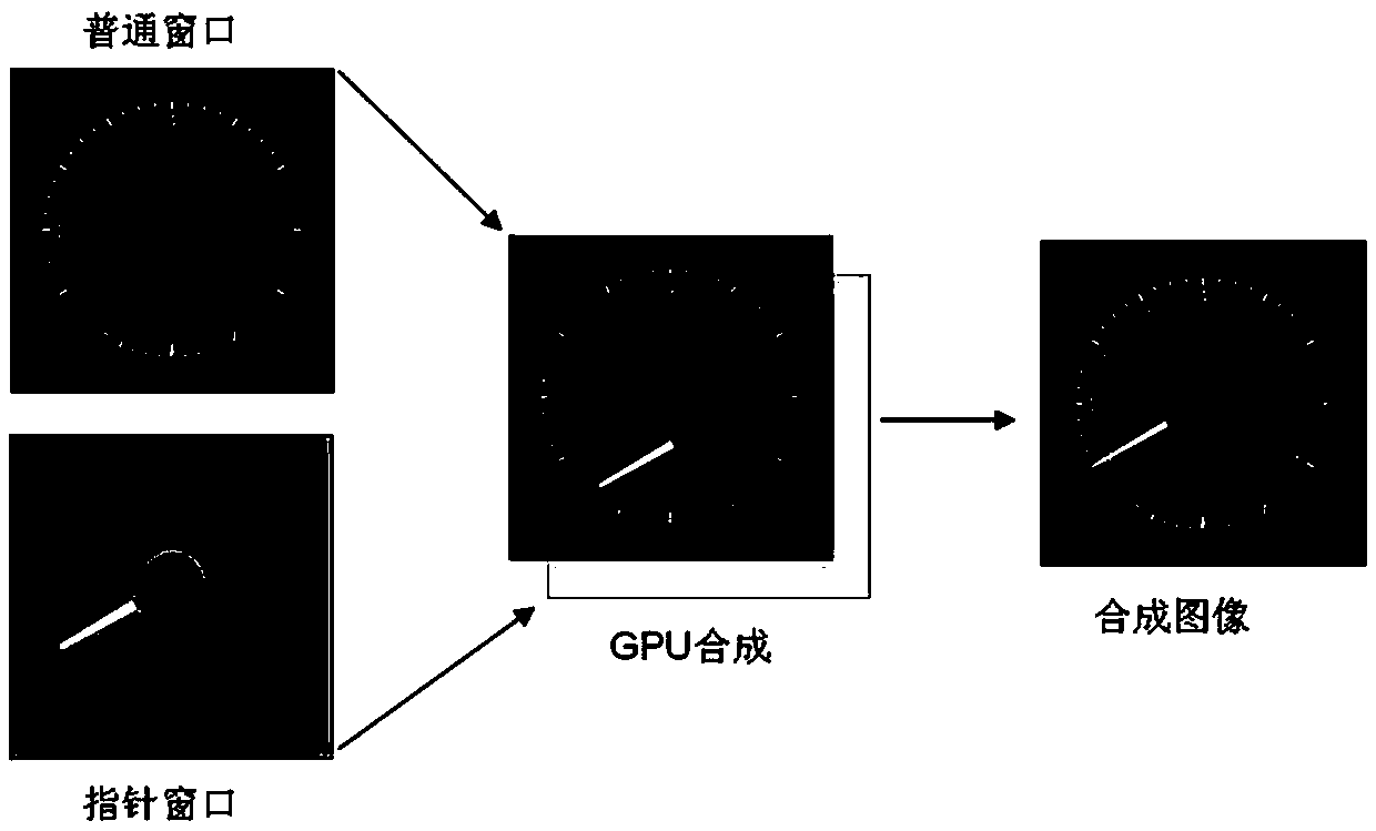
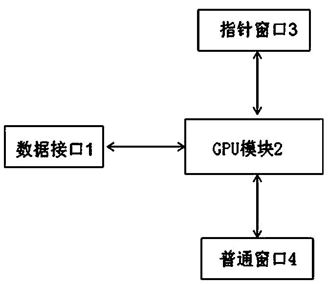
[0046] see figure 1 , is a schematic diagram of the framework of the digital meter pointer display system of the embodiment; the digital meter pointer display system provided by the present invention, the basic structure of the display implementation is to split the application window into two parts:
[0047] 1. The pointer window is implemented using the OpenGL interface.
[0048] 2. Ordinary windows (dials, texts, icons) are implemented using the Qt GUI framework.
[0049] As shown in the table below:
[0050]
[0051] according to figure 1 The display order of the windows in : the pointer window is in the front, and the normal window is in the back. After being synthesized by the GPU, it is displayed as a complete image.
[0052] figure 2 It is a schematic structural diagram of a digital instrument pointer display system according to an embodiment of the present invention. The present invention provides a digital meter pointer display system, said system comprising...
Embodiment 2
[0065] In addition, the present invention also discloses a digital meter pointer display method based on the digital meter pointer display system, such as Figure 4 As shown, it is a flowchart of a digital instrument pointer display method according to an embodiment of the present invention;
[0066] The method comprises the steps of:
[0067] Step 1: Initialize the pointer window;
[0068] Step 2: Query the data interface message to determine whether there is new pointer movement boundary value setting data, if so, go to step 3, otherwise go to step 4;
[0069] Step 3: updating the pointer movement boundary value according to the new pointer movement boundary value setting data;
[0070] Step 4: Determine the current pointer movement state, if the current pointer is in a stopped state, then go to step 2, otherwise go to step 5;
[0071] Step 5: redraw the pointer to a new position according to the pointer motion state and the pointer motion boundary value;
[0072] Step 6...
PUM
Abstract
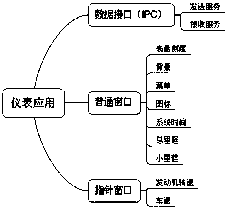
The invention relates to the field of digital instruments, provides a digital instrument pointer display system, and additionally further provides a digital instrument pointer display method. The digital instrument pointer display system is characterized in that the digital instrument pointer display system comprises a pointer window, an ordinary window, a GPU module and a data interface; the datainterface is used for transmitting and receiving external data, and the pointer window is used for displaying the engine rotating speed and the automobile speed according to the data received by thedata interface; and the ordinary window is used for displaying a dial plate, ordinary texts and icons, and the GPU module composites the pointer window and the ordinary window in the order that the pointer window is located in front of the ordinary window and displays a complete digital instrument image. The digital instrument pointer display system achieves the effects that the instrument pointerdisplay accuracy is high, the response real-time performance is high and the visual fluency is high.
Description
technical field [0001] The invention relates to digital instrument technology, in particular to a digital instrument pointer display system and method. Background technique [0002] With the continuous advancement of modern technology, electronic products have been widely used in automobiles and are gradually becoming more intelligent. At present, most of the most common automobile instruments use electromechanical combination instruments. As the information displayed on the instrument panel continues to increase, causing The panel area of the combination instrument is increasing continuously, but the display capability of the existing electromechanical combination vehicle instrument panel in actual application is limited, which cannot meet the increasing needs of vehicle information processing and display. Traditional automotive instrumentation is mainly for some parameters of fuel vehicles, including display and alarm for related information such as fuel volume, oil temp...
Claims
Application Information
Patent Timeline
Application Date:The date an application was filed.
Publication Date:The date a patent or application was officially published.
First Publication Date:The earliest publication date of a patent with the same application number.
Issue Date:Publication date of the patent grant document.
PCT Entry Date:The Entry date of PCT National Phase.
Estimated Expiry Date:The statutory expiry date of a patent right according to the Patent Law, and it is the longest term of protection that the patent right can achieve without the termination of the patent right due to other reasons(Term extension factor has been taken into account ).
Invalid Date:Actual expiry date is based on effective date or publication date of legal transaction data of invalid patent.

