

Telescopic device upturned end and mounting method thereof
A technology of telescopic device and installation method, which is applied to bridge parts, bridges, buildings, etc., can solve the problem of fouling the flange of the beam body and under the bridge, etc., and achieve the effect of simple processing, convenient transportation and placement
Active Publication Date: 2018-08-17
四川铁拓科技有限公司
View PDF8 Cites 0 Cited by
- Summary
- Abstract
- Description
- Claims
- Application Information
AI Technical Summary
Problems solved by technology
[0004] The purpose of the present invention is to provide a warped telescopic device and its installation method in view of the problem that existing telescopic devices contaminate the flange of the beam body and under the bridge
Method used
View moreImage
Smart ImageViewing Examples

Examples
Embodiment 2
[0073] Compared to Example 1, such as Figure 10 As shown, the shape of the warping head 3 in this embodiment is set as a straight line, and the angle α between the straight line and the anchoring profile 1 is 120-150°.
Login to View More PUM
 Abstract
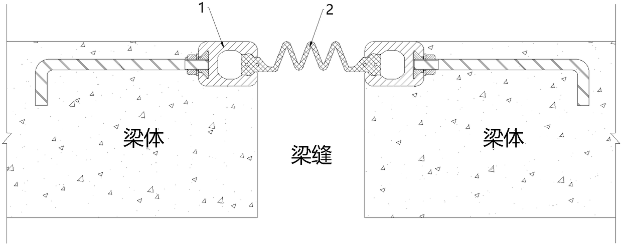
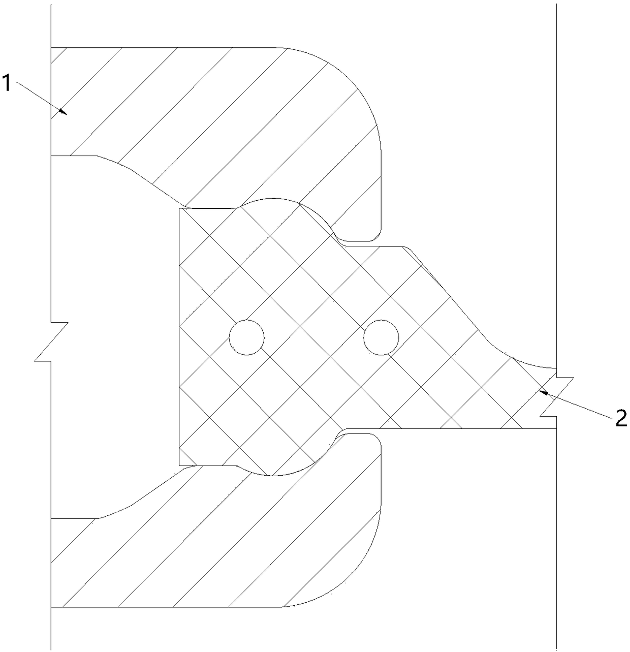
The invention discloses a telescopic device upturned end. One end of the telescopic device upturned end is connected with the end part of an anchoring profile; the other end of the telescopic device upturned end is higher than the end part of the anchoring profile; upturned ends are arranged on two anchoring profiles of a telescopic device; and the two upturned ends are connected with the two sideedges of a waterproof sealing strip. The invention further discloses a mounting method for the telescopic device upturned end; and the telescopic device upturned end is connected with the anchoring profile in a detachable manner. The invention aims at providing the telescopic device upturned end and the mounting method thereof to solve the problem that flanges of a beam body and an underbridge part are stained by using the existing telescopic device. The telescopic device upturned end has the advantages that accumulated water can be blocked, the accumulated water can be prevented from flowingto the flanges of the beam body and the underbridge part, and the mounting is very convenient and fast.
Description
technical field [0001] The invention belongs to the technical field of expansion devices applied to bridge expansion joints, and in particular relates to a warping head of the expansion device and an installation method thereof. Background technique [0002] In order to adapt to the deformation of the bridge beams due to the influence of temperature and stress, gaps must be left between the beams to meet the expansion and contraction deformation of the beams, so as to avoid mutual interference between adjacent beams and damage the stability of the bridge. However, the indwelling of the expansion joints has brought a new hidden danger. The leakage water mixed with oil from the bridge deck enters below the bridge deck through the expansion joints, causing corrosion to the beam body and other auxiliary facilities, thus burdening the maintenance and repair of the bridge. , and even affect the structural durability of the bridge. In order to eliminate the above-mentioned hidden ...
Claims
Login to View More Application Information
Patent Timeline
 IPC IPC(8): E01D19/06
CPCE01D19/06
Inventor刘名君李锐鄢勇罗浚滔何强
Owner四川铁拓科技有限公司