Cavity constant-pressure device
A technology of constant pressure device and cavity, applied in the direction of valve device, safety valve, engine components, etc., can solve the problems of air pressure imbalance, external water vapor ingress, etc., and achieve the effect of simple structure
- Summary
- Abstract
- Description
- Claims
- Application Information
AI Technical Summary
Problems solved by technology
Method used
Image

Examples
Embodiment 1
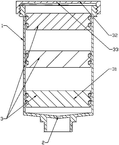
[0027] Embodiment one: if figure 1 As shown, the constant pressure sealing structure is a piston 3, the piston 3 includes at least one layer of sealing plug 31, the sealing plug 31 is adapted to the inner wall of the housing 1, and the fluid is stored in the sealing plug 31 In the area jointly formed with the inner wall of the housing 1 . In this embodiment, the sealing plug 31 is used to move the piston, so as to achieve the effect of changing the internal sealing volume in the constant pressure sealing structure; the design of the multi-layer sealing plug 31 can achieve better sealing and pressure stabilization effects.
[0028] In this embodiment, the piston 3 is provided with three layers of sealing plugs 31 distributed at intervals.
[0029] In this embodiment, the housing 1 is columnar, the vent 2 is arranged at the bottom of the housing 1, and the upper part of the housing 1 is provided with a first sealing cover 32, and the first sealing cover 32 is threadedly connec...
Embodiment 2
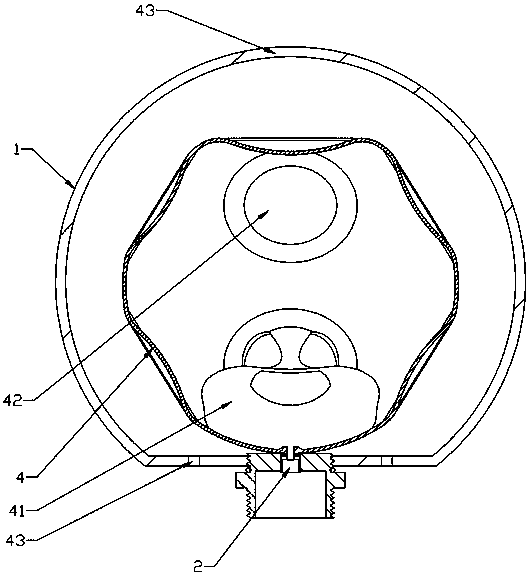
[0030] Embodiment two: if figure 2 As shown, the constant pressure sealing structure is an inflatable balloon 4, and the interior of the inflatable balloon 4 is provided with an inner tank 41 connected to the vent 2, and the fluid is stored in the inflatable balloon 4 In areas other than the inner container 41, the inner container 41 is made of flexible material. In the embodiment, an appropriate amount of air is stored in the inflatable balloon 4, and the inflatable balloon 4 is used to shrink and expand to achieve the effect of changing the internal sealing volume in the constant pressure sealing structure; the inner bag 41 which can be inflated by itself is designed, and when used The fluid medium in the external sealing device is separated from the air in the constant pressure sealing structure by using the liner 41, which can achieve more accurate pressure regulation and at the same time avoid the interference between the external sealing device and the constant pressure...
Embodiment 3
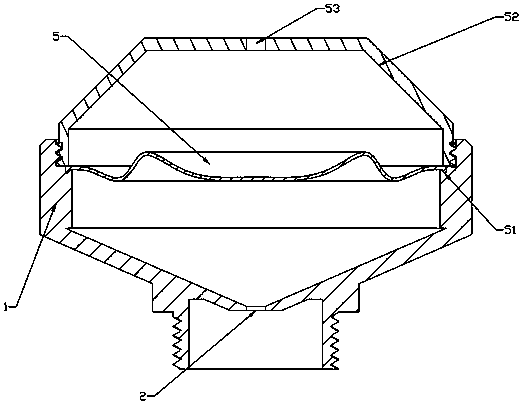
[0033] Embodiment three: as image 3 As shown, the constant pressure sealing structure is a sealing elastic membrane 5, the outer edge of the sealing elastic membrane 5 is provided with a barb 51, and the barb 51 is embedded in the inner wall of the housing 1, and the fluid is stored in the In the area jointly formed by the sealing elastic membrane 5 and the inner wall of the casing 1 . In this embodiment, the sealing elastic membrane 5 divides the housing 1 into two parts from the inside of the housing 1, and the bottom of the housing 1 naturally forms a sealed cavity; in addition, the constant pressure can be changed by utilizing the elasticity of the sealing elastic membrane 5. The effect of the volume of the internal seal cavity in the seal structure.
[0034]In this embodiment, the housing 1 is in the shape of a knob, the vent 2 is arranged at the bottom of the housing 1 , and the upper part of the housing 1 is provided with a second sealing cover 52 , and the second sea...
PUM
 Abstract
Description
Claims
Application Information
 - R&D
- Intellectual Property
- Life Sciences
- Materials
- Tech Scout
- Unparalleled Data Quality
- Higher Quality Content
- 60% Fewer Hallucinations
Browse by: Latest US Patents, China's latest patents, Technical Efficacy Thesaurus, Application Domain, Technology Topic, Popular Technical Reports.
© 2025 PatSnap. All rights reserved.Legal|Privacy policy|Modern Slavery Act Transparency Statement|Sitemap|About US| Contact US: help@patsnap.com