Energy-saving and environment-friendly heating stove
An energy-saving and environmental-friendly heating furnace technology, applied in the heating field, can solve the problems of slow heating, single heat collecting device, and no filtering measures for waste smoke, so as to achieve the effect of improving heating efficiency and sufficient combustion
- Summary
- Abstract
- Description
- Claims
- Application Information
AI Technical Summary
Problems solved by technology
Method used
Image


Examples
Embodiment Construction
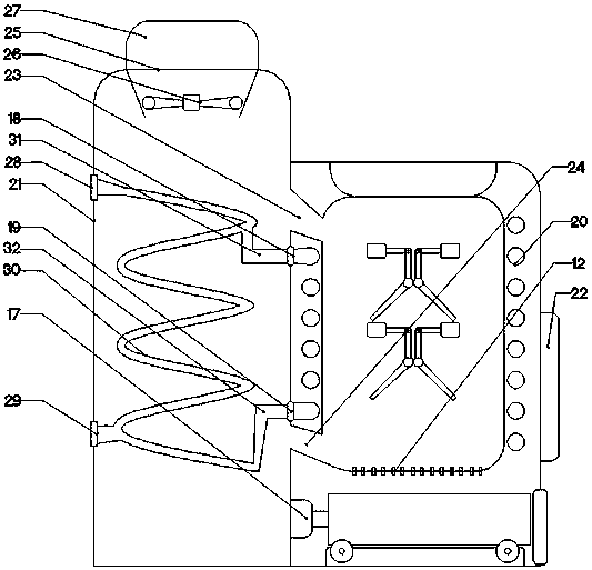
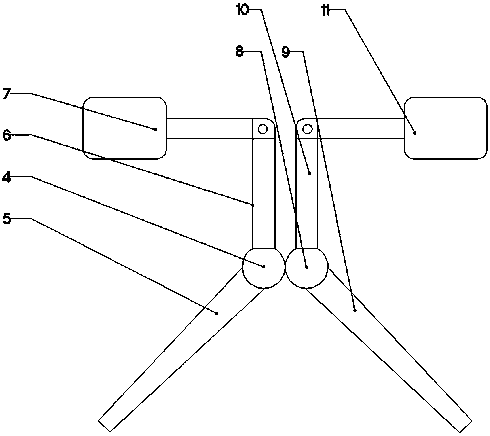
[0021] The present invention is specifically described below in conjunction with accompanying drawing, as Figure 1-5 As shown, it includes a rectangular box-1, and a combustion device is arranged inside the rectangular box-1, and the combustion device is fixedly connected with the rectangular box-1 at the center of the rectangular box-1. 1. The combustion furnace 3 located on the lower surface of the fixed ring 2 and fixedly connected to the fixed ring 2 in the vertical direction, located on the opposite side surface of the combustion furnace 3 and with one end protruding from the rectangular box-1 and the circle connected to the combustion furnace 3 by inserting Shape rotating rod-4, be positioned at the baffle plate-5 that the outer surface of circular rotating rod-4 is fixedly connected with circular rotating rod-4, be positioned at the connecting rod that one end of circular rotating rod-4 is fixedly connected with circular rotating rod-4 6. A linear motor located on the ...
PUM
 Abstract
Description
Claims
Application Information