
Parallel flange channel steel straightening device

A parallel wing and straightening technology, applied in the field of parallel flange channel steel straightening devices, can solve the problems of difficult use of channel steel, collapsed shoulders of webs, collapsed shoulders of channel steel webs, etc., so as to improve production efficiency and product qualification. High efficiency, high-volume continuous straightening structure, and the effect of strong straightening ability

Active Publication Date: 2019-07-02
SHANDONG IRON & STEEL CO LTD
View PDF7 Cites 0 Cited by
  • Summary
  • Abstract
  • Description
  • Claims
  • Application Information

AI Technical Summary

Problems solved by technology

Due to its structural characteristics, the channel steel needs to be straightened in the horizontal direction before use, and it can be used only after the straightening is qualified. Otherwise, it is easy to cause deviations in the force of the channel steel, resulting in instability of the component and affecting the overall structure of the component. safety of use
[0003] For steel structure manufacturing sites that have a large demand for channel steel, there is currently no related equipment that can straighten channel steel with high efficiency. Engineering construction efficiency
In addition, when traditional channel steel straightening equipment is used, the straightening rollers installed on the existing channel steel straightening equipment are likely to cause the "shoulder collapse" defect on the outer side of the channel steel web, which reduces the shape quality of the channel steel after straightening. It will interfere with other components, making it difficult to use channel steel
[0004] In view of the difficulty in straightening parallel flange channel steel and the easy occurrence of "shoulder collapse" defects on the outer side of the web, it is necessary to design a straightening roller structure for parallel flange channel steel

Method used


Image

  • Parallel flange channel steel straightening device
  • Parallel flange channel steel straightening device

Examples


Embodiment Construction

[0023] The present invention will be described in detail below with reference to the accompanying drawings and examples. Each example is provided by way of explanation of the invention, not limitation of the invention. In fact, those skilled in the art will recognize that modifications and variations can be made in the present invention without departing from the scope or spirit of the invention. For example, features illustrated or described as part of one embodiment can be used on another embodiment to yield a still further embodiment. Therefore, it is intended that the present invention includes such modifications and variations as come within the scope of the appended claims and their equivalents.

[0024] In the description of the present invention, the terms "longitudinal", "transverse", "upper", "lower", "front", "rear", "left", "right", "vertical", "horizontal", " The orientations or positional relationships indicated by "top", "bottom", etc. are based on the orienta...


PUM

PropertyMeasurementUnit
angleaaaaaaaaaa

Abstract

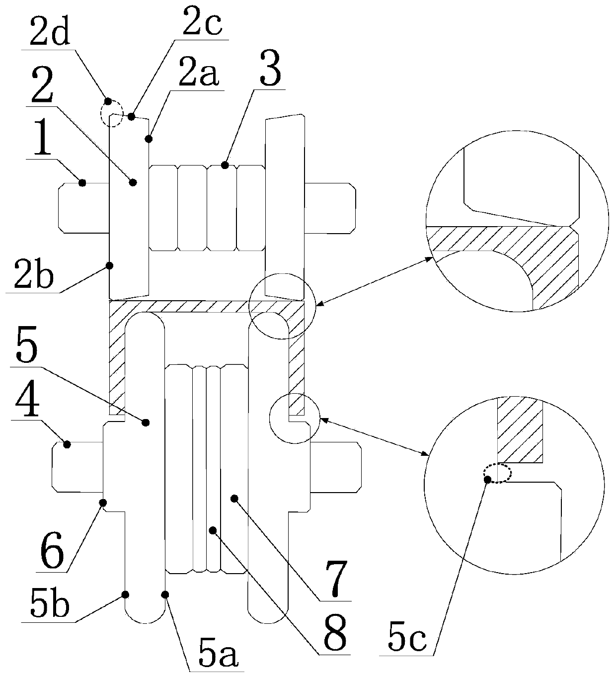
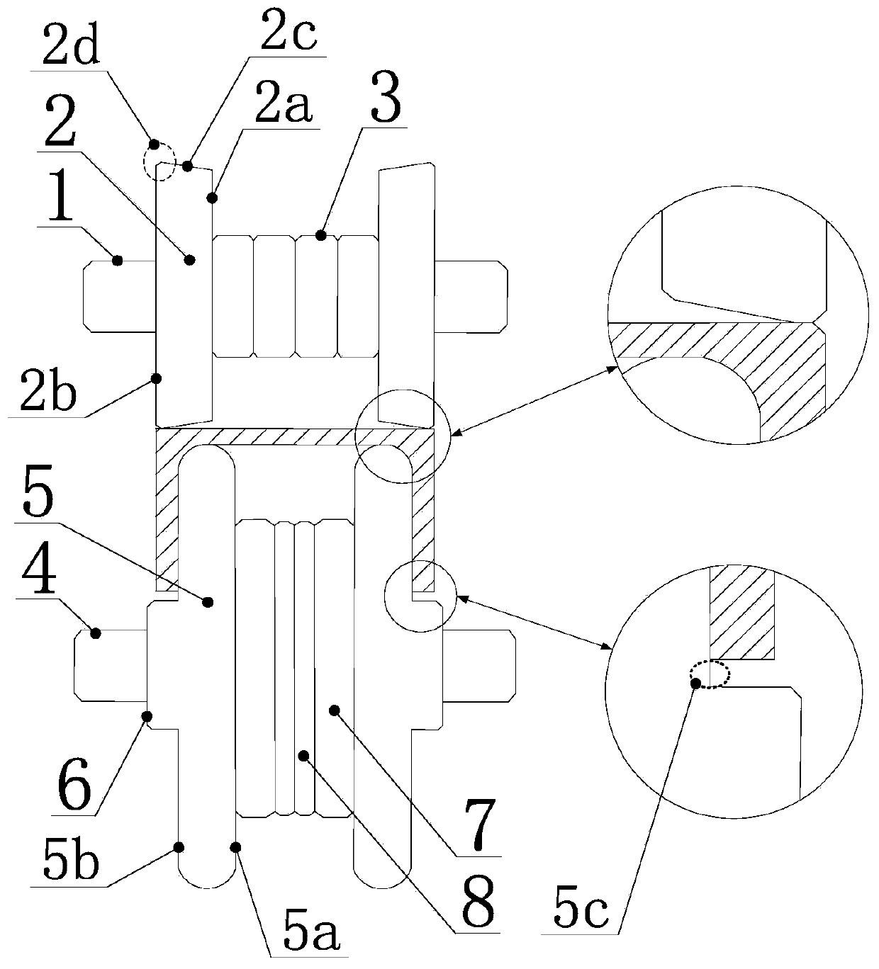
A parallel wing flange steel channel straightening device comprises an equipment machine frame, an upper straightening assembly and a lower straightening assembly. The upper straightening assembly comprises an upper straightening roller, an upper straightening plate and an upper washer. The lower straightening assembly comprises a lower straightening roller, a lower straightening plate and a lowerwasher. The straightening force outer edge and the top end of the outer edge of the lower straightening plate are arranged in a spaced mode and form a straightening gap used for allowing steel channel webs to pass. Based on the structure, steel channel wing flanges are located in a space formed by the upper straightening assembly and the lower straightening assembly after combination, a straightening transition face is formed between the straightening plane of the lower straightening plate and a straightening boss and can limit the size of the steel channels, thus, deformation of the steel channels in the steel channel straightening process can be avoided, and the defect of sloping shoulder of the steel channel webs is avoided. The problem of the sloping shoulder defect of the outer sidesof the steel channel webs can be effectively solved, the operation stability of workpieces in the straightening process is improved, thus, the production efficiency and product percent of pass are improved, and the straightening device is suitable for batch straightening operation.

Description

technical field [0001] The invention relates to the technical field of workpiece straightening equipment, and more specifically relates to a parallel flange channel steel straightening device. Background technique [0002] Channel steel is a C-shaped section steel, which is widely used in various building structures, bridges, brackets, etc. Due to its structural characteristics, the channel steel needs to be straightened in the horizontal direction before use, and it can be used only after the straightening is qualified. Otherwise, it is easy to cause deviations in the force of the channel steel, resulting in instability of the component and affecting the overall structure of the component. safety of use. [0003] For steel structure manufacturing sites that have a large demand for channel steel, there is currently no related equipment that can straighten channel steel with high efficiency. Engineering construction efficiency. In addition, when traditional channel steel s...

Claims


Application Information

Patent Timeline
Patent Type & Authority Patents(China)
IPC IPC(8): B21D3/05
CPCB21D3/05
Inventor 付常伟王中学张秀山赵西义任伟赵新华任维杰
Owner SHANDONG IRON & STEEL CO LTD
Learn More