Automatic forming machine and method for transformer enameled wire U-shaped coils

An automatic forming machine, enameled wire technology, applied in the direction of inductor/transformer/magnet manufacturing, coil manufacturing, electrical components, etc., can solve the problems of low work efficiency, high labor intensity of operators, and inability to guarantee the accuracy of pin spacing, etc. Improve work efficiency and ensure the effect of forming accuracy

Pending Publication Date: 2020-11-17
亚元科技(宜昌)电子有限公司
View PDF0 Cites 0 Cited by
  • Summary
  • Abstract
  • Description
  • Claims
  • Application Information

AI Technical Summary

Problems solved by technology

[0003] At present, the bending and forming of U-shaped coils is usually done by hand. The work efficiency is relatively low, and the labor intensity of the workers is high. During the manual bending process, the contact between the pins cannot be guaranteed. Spacing accuracy requirements, and the bending angle cannot be guaranteed, so the quality of the product cannot be guaranteed

Method used


Image

  • Automatic forming machine and method for transformer enameled wire U-shaped coils
  • Automatic forming machine and method for transformer enameled wire U-shaped coils
  • Automatic forming machine and method for transformer enameled wire U-shaped coils

Examples


Embodiment 1

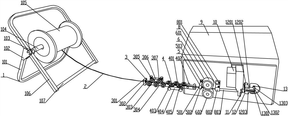
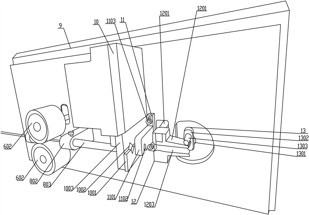
[0054] See Figure 1-4 , An automatic forming machine for transformer enameled wire U-shaped coils, which includes a copper wire coil support frame 1 for storing copper wire coils; and also includes a main box 9 whose front side wall is fixed for alignment A feeding guide structure 5 for feeding and guiding copper wire raw materials. The station before the feeding guide structure 5 is provided with a vertical straightening structure 3 and a transverse straightening structure 4 for compound straightening of the copper wire. The station after the feeding guide structure 5 is provided with a traction power device 6 for traction of the copper wire, and the output end of the traction power device 6 is provided with a discharge guide structure for guiding the copper wire after straightening 8. The output end of the discharging guide structure 8 is provided with a cutting mechanism 10 for cutting the copper wire. The station after the cutting mechanism 10 is provided with a rear guide...

Embodiment 2

[0068] The automatic forming machine performs the bending forming method of the U-shaped winding skeleton of the transformer enameled wire, which includes the following steps:

[0069] Step 1: Place the copper wire storage tray 105 on the copper wire coil support frame 1;

[0070] Step two, lead the copper wire 2 out, pass through the vertical straightening structure 3, the lateral straightening structure 4 and the feeding guide structure 5 in turn, and then introduce the traction power device 6, start the traction power device 6, and pass through the active roller 601 The rotation of the moving roller 602 drives the copper wire 2 to be transported forward;

[0071] Step 3: The copper wire is drawn and straightened and transported to the discharging guide structure 8, and from the discharging guide structure 8 through the cutting mechanism 10, the rear guide plate structure 11 and the telescopic pressing mechanism 12 to the bending mechanism 13;

[0072] Step 4: When the length of the...


PUM


Abstract

The invention provides an automatic forming machine and method for a transformer enameled wire U-shaped coil, and the method comprises the steps: fixing a feeding guide structure for the feeding guideof a copper wire raw material on the front side wall of a main case, and arranging a traction power device for the traction of a copper wire at a station behind the feeding guide structure; the output end of the traction power device is provided with a discharging guide structure used for guiding straightened copper wires, the output end of the discharging guide structure is provided with a cutting-off mechanism used for cutting off the copper wires, and a rear guide plate structure is arranged on a station behind the cutting-off mechanism; the telescopic pressing mechanism used for pressingthe copper wire is arranged behind the rear guide plate structure, and a bending mechanism is arranged at the station behind the telescopic pressing mechanism. A conventional manual operation mode isreplaced, and the working efficiency is greatly improved.

Description

Technical field [0001] The invention relates to the field of electronic component processing equipment, in particular to an automatic forming machine and method for a U-shaped coil of enameled wire of a transformer. Background technique [0002] In the production process of small transformer electronic components, it is necessary to wind the enameled wire. The internal coil is a U-shaped coil, which is made of thick copper wire, and the distance between the two pins and The accuracy of the bending angle is high. [0003] At present, the manual bending method is usually used for the bending of U-shaped coils. The manual bending method is less efficient and the labor intensity of the operators is high. During the manual bending process, it is impossible to guarantee the contact between the pins. The spacing accuracy is required, and the bending angle cannot be guaranteed, and the quality of the product cannot be guaranteed. Summary of the invention [0004] The purpose of the presen...

Claims


Application Information

Patent Timeline
Patent Type & Authority Applications(China)
IPC IPC(8): H01F41/082H01F41/096H01F41/06H01F41/076
CPCH01F41/06H01F41/076H01F41/082H01F41/096
Inventor 代圣平
Owner 亚元科技(宜昌)电子有限公司
Why Eureka
Try Eureka