A detection method of image plane defocus amount of optical system

An optical system and detection method technology, applied in the field of space optics, can solve the problem of inability to detect the defocus of the image plane, and achieve the effect of accurate detection

Active Publication Date: 2019-09-10
CHANGCHUN INST OF OPTICS FINE MECHANICS & PHYSICS CHINESE ACAD OF SCI
View PDF6 Cites 0 Cited by
  • Summary
  • Abstract
  • Description
  • Claims
  • Application Information

AI Technical Summary

Problems solved by technology

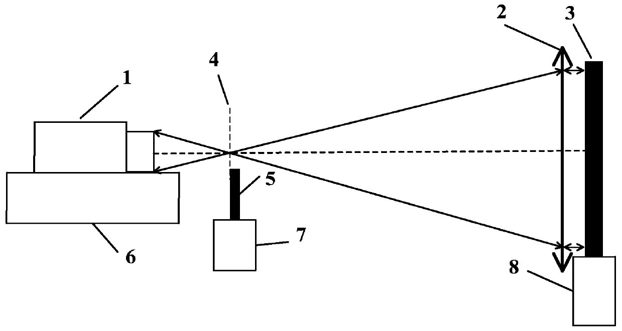
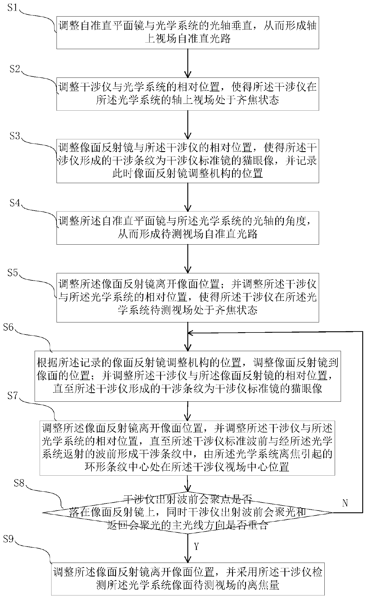
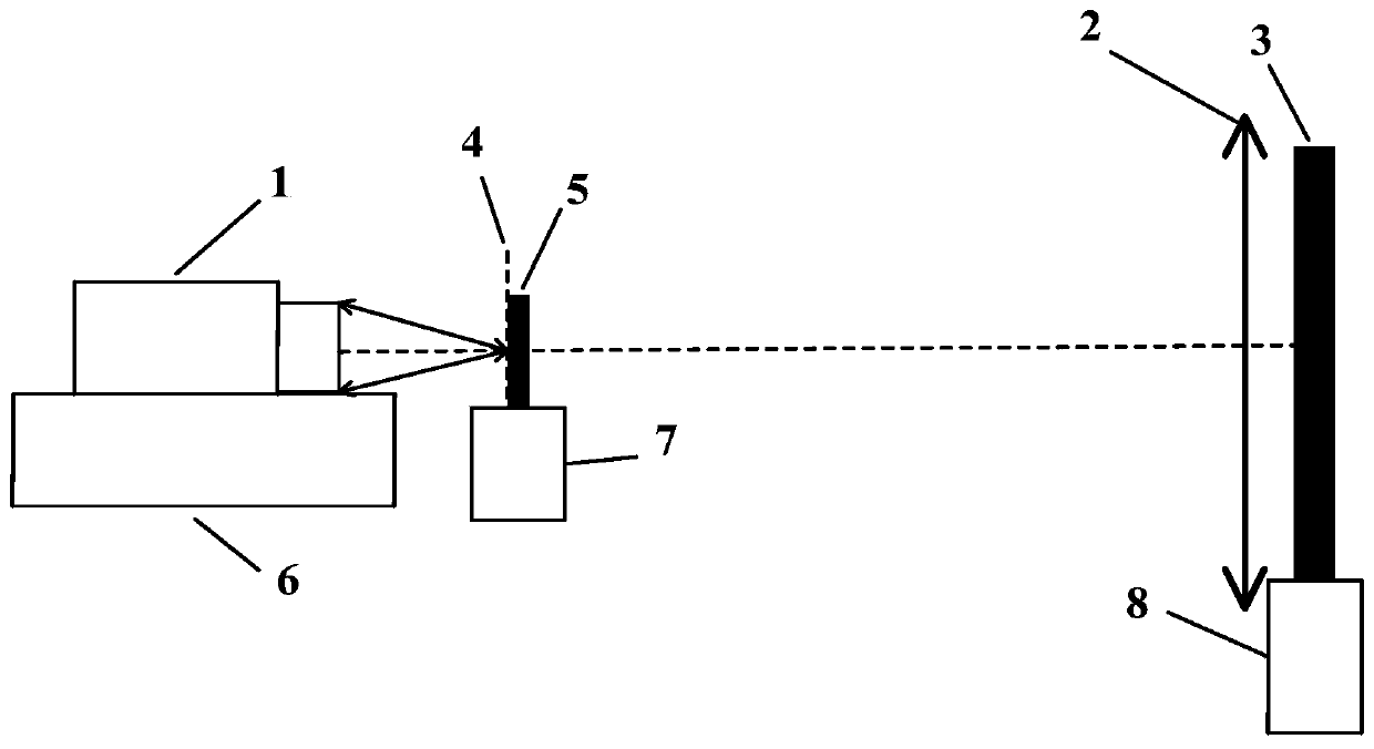
[0004] In view of the problem that the existing optical system based on the self-collimation principle of the interferometer cannot detect the defocus amount of the image plane, the embodiment of the present invention proposes a detection method for the defocus amount of the image plane of the optical system

Method used


Image

  • A detection method of image plane defocus amount of optical system
  • A detection method of image plane defocus amount of optical system
  • A detection method of image plane defocus amount of optical system

Examples


Embodiment Construction

[0024] In order to enable those skilled in the art to better understand the solutions of the present invention, the following will clearly and completely describe the technical solutions in the embodiments of the present invention in conjunction with the drawings in the embodiments of the present invention. Obviously, the described embodiments are only It is an embodiment of a part of the present invention, but not all embodiments. Based on the embodiments of the present invention, all other embodiments obtained by persons of ordinary skill in the art without creative efforts shall fall within the protection scope of the present invention.

[0025] The terms "first", "second", "third", "fourth", etc. (if any) in the description and claims of the present invention and the above drawings are used to distinguish similar objects and not necessarily Describe a specific order or sequence. It is to be understood that the terms so used are interchangeable under appropriate circumstan...


PUM


Abstract

The embodiment of the invention discloses a method for detecting the defocus amount of an image plane of an optical system. The method for detecting the defocus amount of the image plane of the optical system provided in the embodiment of the present invention is based on the parfocal optical path of the interferometer and the optical system, by adjusting the interferometer so that the focus of the outgoing wavefront can not only accurately fall on the image of the optical system At the same time, the direction of the main light rays of the outgoing wavefront convergent light and the return convergent light of the interferometer coincide, so as to expand the existing functions of the laser interferometer and accurately realize the detection of the defocus amount of the image plane of the optical system. Further, the imaging quality of the optical system can be evaluated by detecting the defocus amount, thereby improving the adjustment efficiency of the optical system and improving the imaging quality.

Description

technical field [0001] The invention relates to the technical field of space optics, in particular to a method for detecting the defocus amount of an image plane of an optical system. Background technique [0002] When the optical system is installed and adjusted on the ground (especially when the long focal length reflective telescope is installed and adjusted on the ground), the self-collimation detection method based on the interferometer is often used to obtain the wave aberration of different fields of view of the misaligned system, and then the algorithm is used to obtain The amount of misalignment of the mirror body of the optical system, and then adjust the posture of the mirror body of the optical system, and adjust the optical system to the best image quality state. The self-collimation detection method adjusts the attitude of the interferometer so that the converging point of the outgoing laser spherical wave coincides with the converging point returning through t...

Claims


Application Information

Patent Timeline
Patent Type & Authority Patents(China)
IPC IPC(8): G01M11/00
Inventor 马宏财苏东奇胡春晖张冬旭
Owner CHANGCHUN INST OF OPTICS FINE MECHANICS & PHYSICS CHINESE ACAD OF SCI
Why Eureka
Try Eureka