Laser machine and camera linking control method, device and system

A technology of cameras and lasers, applied in the parts, optics, instruments and other directions of TV systems, can solve the problems of poor lighting effect, solidification of mechanical structure, and low definition of objects.

Inactive Publication Date: 2018-08-21
HANGZHOU HIKVISION DIGITAL TECH
View PDF12 Cites 22 Cited by
  • Summary
  • Abstract
  • Description
  • Claims
  • Application Information

AI Technical Summary

Problems solved by technology

[0004] At present, the mechanical structure of the laser structure adjustment module on the market is relatively solid, which leads to the fixed light supplementary area formed by the laser emitted by the laser module.
When the object being photographed moves, the camera will follow the rotation of the object. Since the laser fill light area is fixed, when the object moves to the edge position of the fill light area or moves out of the fill light area, because the edge position of the fill light area and The clarity of the fill light in areas other than the fill light area is low, and the fill light area of ​​the existing laser fill light is difficult to adjust, resulting in low definition of the captured object and poor fill light effect

Method used


Image

  • Laser machine and camera linking control method, device and system
  • Laser machine and camera linking control method, device and system
  • Laser machine and camera linking control method, device and system

Examples


Embodiment Construction

[0093] The following will clearly and completely describe the technical solutions in the embodiments of the present invention with reference to the accompanying drawings in the embodiments of the present invention. Obviously, the described embodiments are only some, not all, embodiments of the present invention. Based on the embodiments of the present invention, all other embodiments obtained by persons of ordinary skill in the art without making creative efforts belong to the protection scope of the present invention.

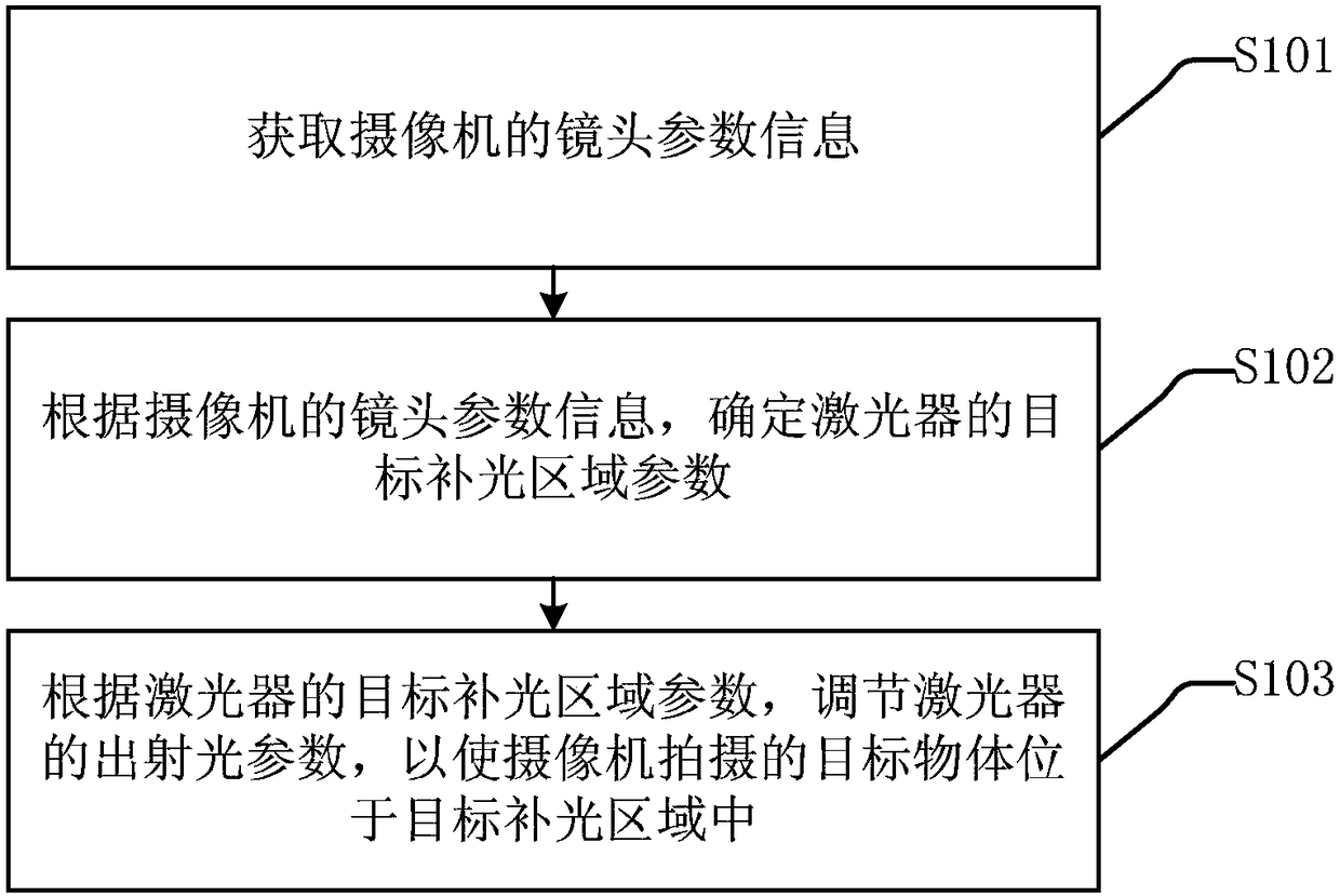
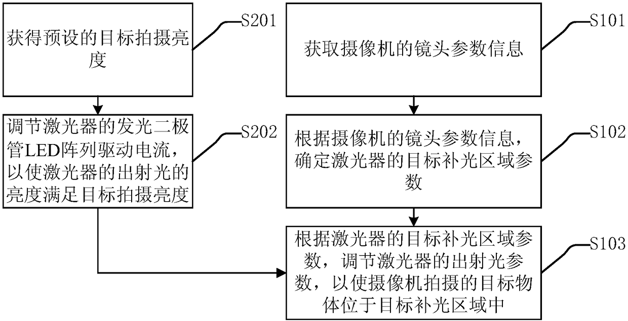
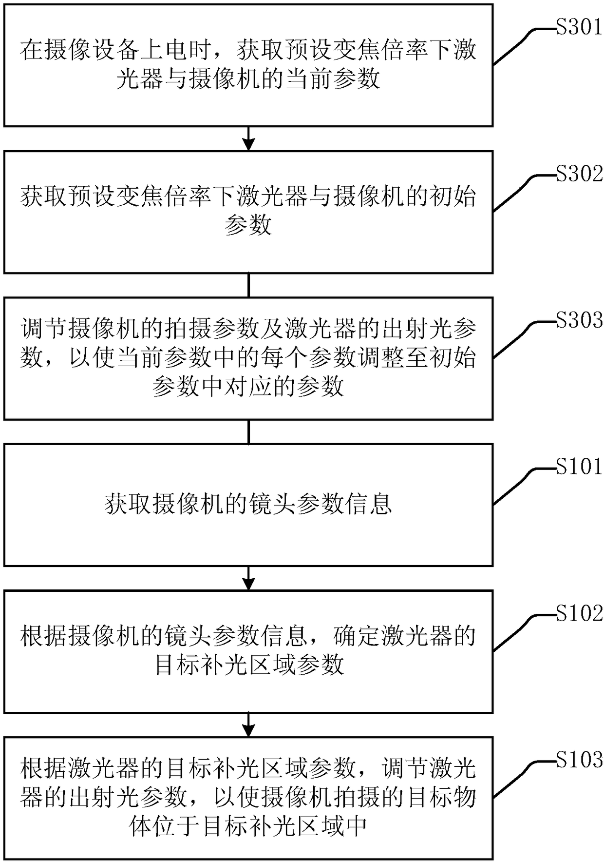
[0094] In order to improve the definition of an object photographed by a camera, embodiments of the present invention provide a method, device and system for linkage control of a laser and a camera.

[0095] The following firstly introduces a linkage control method of a laser and a camera provided by an embodiment of the present invention.

[0096] It should be noted that the execution subject of the linkage control method for a laser and a camera provided in ...


PUM


Abstract

The invention provides a laser machine and camera linking control method, device and system, which are applied in a shooting device, comprising the laser machine and the camera. The camera moves alongthe moving of a target object. The laser machine and camera linking control method comprises the steps that the parameter information of lens of the camera is obtained, wherein the parameter information of lens of the camera is corresponding to the shooting area of the camera; the parameter of a target light-filling area of the laser machine can be determined based on the lens parameter information of the camera; the emergent light parameter of the laser machine can be adjusted based on the target light-filling area of the laser machine, so that the target object shot by the camera can be placed in the target light-filling area. The invention is advantageous in that the definition of the object shot by the camera can be increased.

Description

technical field [0001] The invention relates to the technical field of video monitoring, in particular to a method, device and system for linkage control of a laser and a camera. Background technique [0002] Video surveillance is an important part of the security system, and the most important video surveillance equipment is a surveillance camera. Surveillance cameras are mainly divided into gun-type equipment, hemispherical equipment and dome-type equipment in terms of appearance, and there are also distinctions between analog monitoring and network monitoring. They are widely used in many security fields such as banking, transportation, and safe cities. Because the dome camera equipment can use the stepper motor to quickly and accurately position and rotate the camera according to the actual motion of the object being photographed, it can track the photographed object very well, and it plays a very important role in the fields of urban public security and traffic monitori...

Claims


Application Information

Patent Timeline
Patent Type & Authority Applications(China)
IPC IPC(8): H04N5/235H04N5/232G03B15/05G03B15/03
CPCG03B15/05H04N23/67H04N23/71H04N23/74
Inventor 万心谷川刘重斌
Owner HANGZHOU HIKVISION DIGITAL TECH
Why Eureka
Try Eureka