Movable dust removing vehicle

A dust removal vehicle and mobile technology, applied in the direction of cleaning method using gas flow, cleaning method and utensils, chemical instruments and methods, etc., can solve the problems such as inconvenient cleaning effect, achieve good practicability, convenient and flexible location, Convenient and flexible adjustment effect

Inactive Publication Date: 2018-08-24
叶凯雨
View PDF6 Cites 4 Cited by
  • Summary
  • Abstract
  • Description
  • Claims
  • Application Information

AI Technical Summary

Problems solved by technology

This kind of fixed dust collector is inconvenient to clean the dust generated during the catalyst manufacturing mobile unloading process

Method used


Image

  • Movable dust removing vehicle

Examples


Embodiment

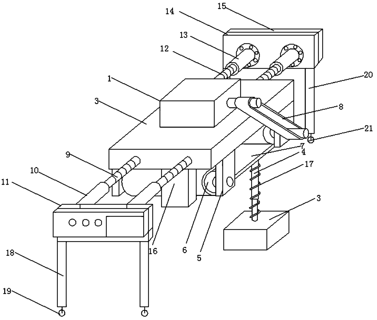
[0020] Such as figure 1 The mobile dust removal vehicle shown includes a traveling mechanism, a control mechanism, a drive motor 1, an assembly seat 2 and at least one set of dust collection mechanisms 3, and the control mechanism and drive motor 1 are fixed on the upper surface of the assembly seat 2, and the suction The dust mechanism 3 is located under the assembly seat 2, and the dust removal vehicle also includes two sets of fixed frames 5, two sets of rotating shafts, two sets of rotating rollers 6, a first transmission belt 7, a second transmission belt 8, and two sets of first threaded connecting rods 9. Two groups of first threaded connecting pipes 10, first fixing parts 11, two groups of second threaded connecting rods 12, two groups of second threaded connecting pipes 13 and second fixing parts 14, and the fixing frames 5 are arranged along the two sides of the assembly seat 2 respectively. The side width direction is set, the fixed frame 5 is also provided with two...


PUM


Abstract

The invention relates to dust removing equipment, in particular to a movable dust removing vehicle which comprises a traveling mechanism, a control mechanism, a drive motor, an assembling base and atleast one dust absorbing mechanism. The control mechanism and the drive motor are fixedly arranged on the upper end face of the assembling base. The dust absorbing mechanism is arranged below the assembling base. The dust removing equipment further comprises two fixing frames, two rotating shafts, two rotating rollers, a first transmission belt, a second transmission belt, two first thread connecting rods, two first thread connecting pipes, a first fixing part, two second thread connecting rods, two second thread connecting pipes and a second fixing part. According to the movable dust removingvehicle, by means of the arrangement, the drive motor is driven by the second transmission belt to drive the rotating shafts to rotate and meanwhile drives the first transmission belt to rotate, thus, the dust absorbing mechanism is driven to move in a reciprocating manner in the length direction, and fly dust in all areas can be adsorbed dynamically. The position of the movable dust removing vehicle can be adjusted conveniently and flexibly, the use limitation is low, the dust removing effect is good, and practicality is good.

Description

technical field [0001] The invention relates to a dust removal device, in particular to a mobile dust removal vehicle. Background technique [0002] Smelting workshops such as converters and blast furnaces in the iron and steel industry need to send the required metallurgical raw materials to the feeding platform of the feeding bay through belt conveyors, and then unload the metallurgical raw materials into the silo through the mobile unloading trolley. The mobile unloading trolley moves linearly on the feeding platform, and moves back and forth between multiple unloading ports for unloading. [0003] The above-mentioned mobile unloading process will generate a lot of dust, which will cause smog and dust on the loading platform, and the environment is very bad, which seriously threatens the physical and mental health of operators. In order to protect the health of operators, it is common practice to use a dust collector to purify the air. [0004] The industrial dust colle...

Claims


Application Information

Patent Timeline
Patent Type & Authority Applications(China)
IPC IPC(8): B08B5/04
CPCB08B5/04
Inventor 叶凯雨
Owner 叶凯雨
Why Eureka
Try Eureka