Frame welding positioning structure

A welding positioning and frame technology, applied in welding equipment, auxiliary welding equipment, welding/cutting auxiliary equipment, etc., can solve problems such as inability to achieve positioning

Active Publication Date: 2018-08-24
唐山市众基钢结构有限公司
View PDF6 Cites 6 Cited by
  • Summary
  • Abstract
  • Description
  • Claims
  • Application Information

AI Technical Summary

Problems solved by technology

[0002] For example, the patent number CN201610814146.9 is a frame welding positioning device, which includes a horizontally arranged installation platform and a column connected to the bottom of the installation platform to form a leg. The two sides and the rear of the installation platform are vertically provided with baffle plates, so A crossbeam is horizontally arranged on the side baffles on both sides, and an installation groove penetrating up and down is opened in the middle of the installation platform. Positioning components are arranged on the four sides of the installation groove, and a corresponding installation on the crossbeam is arranged above the installation groove. The pressure component, the lower part of the installation groove is provided with a supporting plate component, the inner wall of the two side baffles is provided with a clamping component opposite to the left and right, and the frame welding positioning device is also connected with a control device; the disadvantage of this invention is that it cannot Realize positioning in three degrees of freedom in space

Method used


Image

  • Frame welding positioning structure
  • Frame welding positioning structure
  • Frame welding positioning structure

Examples


specific Embodiment approach 1

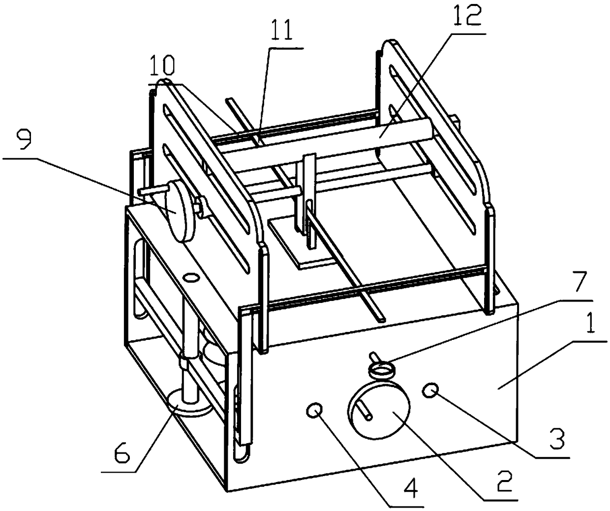
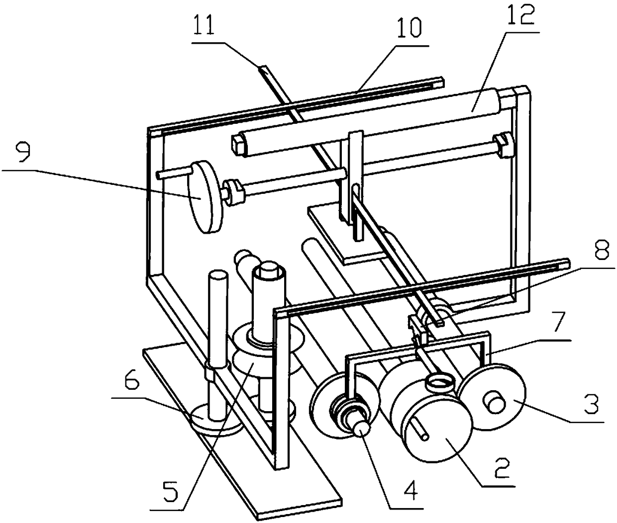
[0037] Combine below Figure 1-18 Describe this embodiment, a frame welding positioning structure, including the whole machine bracket 1, the power mechanism 2, the lateral movement mechanism 3, the vertical movement mechanism 4, the transmission mechanism I5, the transmission mechanism II6, the switching mechanism 7, the switching fixed block 8, Horizontal movement mechanism 9, sliding support rod 10, positioning 11 and sliding column 12, the switching mechanism 7 includes a shift fork 7-1 and a switching sliding block 7-2, and the shift fork 7-1 includes a shift fork body 7-1-1 , pushing body 7-1-2 and switching sliding hole 7-1-3, described pushing body 7-1-2 is provided with two, and two pushing bodies 7-1-2 are respectively welded on shift fork body 7-1 On the left and right sides of the lower end of -1, the switching sliding hole 7-1-3 is arranged at the middle end of the shift fork body 7-1-1, and the switching sliding block 7-2 includes a spring mounting column 7-2-1 a...

specific Embodiment approach 2

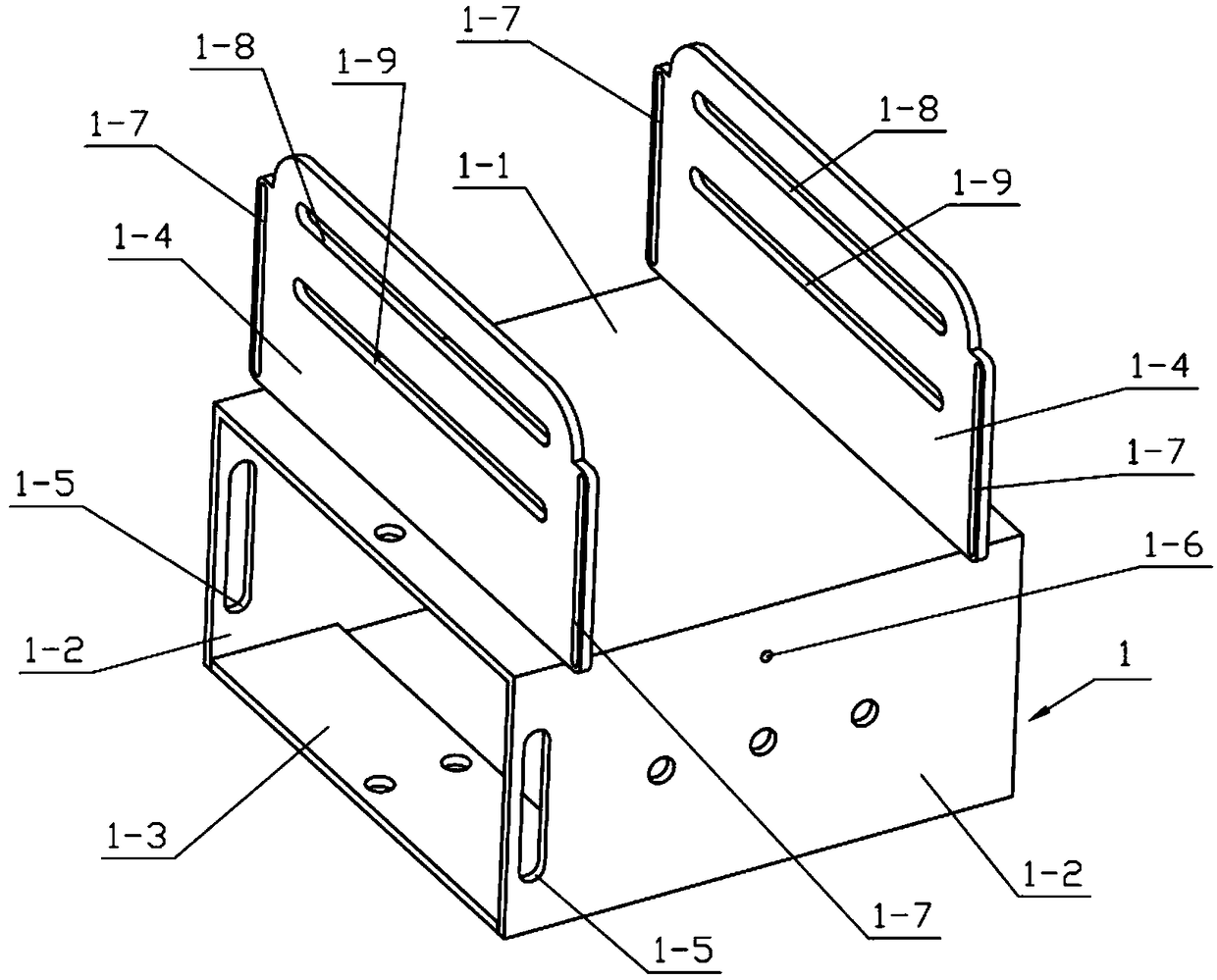
[0038] Combine below Figure 1-18 Describe this embodiment, this embodiment will further explain Embodiment 1, the whole machine support 1 includes a workbench 1-1, a support base plate 1-2, a base plate 1-3, a sliding support plate 1-4, and a vertical sliding groove Ⅰ1-5, switching sliding port 1-6, vertical sliding groove Ⅱ1-7, horizontal sliding groove Ⅰ1-8 and horizontal sliding groove Ⅱ1-9, the supporting bottom plate 1-2 and the sliding supporting plate 1-4 are respectively provided with two , two support base plates 1-2 are respectively fixedly connected to the left and right sides of the lower end of the workbench 1-1, two sliding support plates 1-4 are respectively fixedly connected to the front and rear sides of the upper end of the workbench 1-1, and the base plates 1-3 The two ends of the two support base plates 1-2 are respectively fixedly connected, the switch sliding port 1-6 is arranged on the support base plate 1-2 on the right side, and there are two vertical...

specific Embodiment approach 3

[0039] Combine below Figure 1-18 Describe this embodiment, this embodiment will further explain the second embodiment, the power mechanism 2 includes a power shaft 2-1, a rotating handle 2-2 and a power gear 2-3, and the rotating handle 2-2 is fixedly connected to the power shaft At the right end of 2-1, the power gear 2-3 is fixedly connected to the power shaft 2-1, and the two ends of the power shaft 2-1 are respectively connected to the two support base plates 1-2 in rotation.


PUM


Abstract

The invention relates to a positioning device, in particular to a frame welding positioning structure. The frame welding positioning structure comprises a whole machine bracket, a power mechanism, a transverse movement mechanism, a vertical movement mechanism, a transmission mechanism I, a transmission mechanism II, a switching mechanism, a switching fixed block, a horizontal movement mechanism, asliding support rod, a positioning part and a sliding column. The power mechanism drives the transverse movement mechanism and the vertical movement mechanism to rotate simultaneously, and the switching mechanism controls the power switching of the lateral motion mechanism and the vertical motion mechanism when the switching fixed block slides. When the transverse movement mechanism moves, the positioning part is driven to slide on the sliding support rod, the lateral position of the positioning part is changed, when the vertical movement mechanism rotates, the vertical movement mechanism drives the sliding support rod to move up and down, the sliding support rod drives the positioning part in a sliding groove to slide to change the upper and lower positions of the positioning part, a horizontal moving handle is turned to drive the positioning part to move horizontally, and the positioning part can be controlled and moved by three freedom degrees in the space.

Description

technical field [0001] The invention relates to a positioning device, in particular to a frame welding positioning structure. Background technique [0002] For example, the patent number CN201610814146.9 is a frame welding positioning device, which includes a horizontally arranged installation platform and a column connected to the bottom of the installation platform to form a leg. The two sides and the rear of the installation platform are vertically provided with baffle plates, so A crossbeam is horizontally arranged on the side baffles on both sides, and an installation groove penetrating up and down is opened in the middle of the installation platform. Positioning components are arranged on the four sides of the installation groove, and a corresponding installation device installed on the crossbeam is arranged above the installation groove. The pressure component, the lower part of the installation groove is provided with a supporting plate component, the inner wall of t...

Claims


Application Information

Patent Timeline
Patent Type & Authority Applications(China)
IPC IPC(8): B23K37/04
CPCB23K37/0426
Inventor 李凤春
Owner 唐山市众基钢结构有限公司
Why Eureka
Try Eureka