
Glass processing clamping device

A glass and support column technology is applied in the field of glass processing and clamping devices, which can solve the problems of panel glass pollution, operator accidents, and delayed processing progress, and achieve the effect of effective clamping, avoiding accidents, and preventing accidental falling off.

Pending Publication Date: 2018-08-24
江西昌浩实业有限公司
View PDF0 Cites 0 Cited by
  • Summary
  • Abstract
  • Description
  • Claims
  • Application Information

AI Technical Summary

Problems solved by technology

[0002] During the coating process, the panel glass to be processed needs to be transported to the coating equipment through the corresponding transmission line. After the coating operation is completed, the coated panel glass is transported out, and the equipment for transmitting the panel glass is in the transmission panel glass. During the process, the panel glass needs to be grasped and transported one by one. Since the surface of the panel glass cannot be polluted during the coating of the panel glass, this puts forward higher requirements for the panel glass grasping operation. However, the existing panel glass grasping The mechanism cannot adapt to this requirement, which will easily cause pollution and slow speed and low efficiency during the grabbing process of the panel glass, and even the danger of falling glass will occur during the grabbing process of the panel glass. Therefore, the existing panel glass grabbing mechanism There are many deficiencies, such as:
[0003] 1. In the prior art, the clamping device for glass processing is clamped by grip force. Although this method is simple, it may cause property damage due to glass falling when insufficient force is used. In severe cases, it is more likely to cause accidents to the operator. And it can't clamp larger glass, and can't meet the purpose of clamping most of the glass;
[0004] 2. The structure of the device used for glass clamping in the prior art is relatively simple, and the stability is poor. It is easy to cause the clamped glass to fall and injure the toes, which is not conducive to the progress of glass processing and delays the processing progress. more cumbersome to control

Method used


Image

  • Glass processing clamping device
  • Glass processing clamping device
  • Glass processing clamping device

Examples


Embodiment Construction

[0026] The following will clearly and completely describe the technical solutions in the embodiments of the present invention with reference to the accompanying drawings in the embodiments of the present invention. Obviously, the described embodiments are only some, not all, embodiments of the present invention. Based on the embodiments of the present invention, all other embodiments obtained by persons of ordinary skill in the art without making creative efforts belong to the protection scope of the present invention.

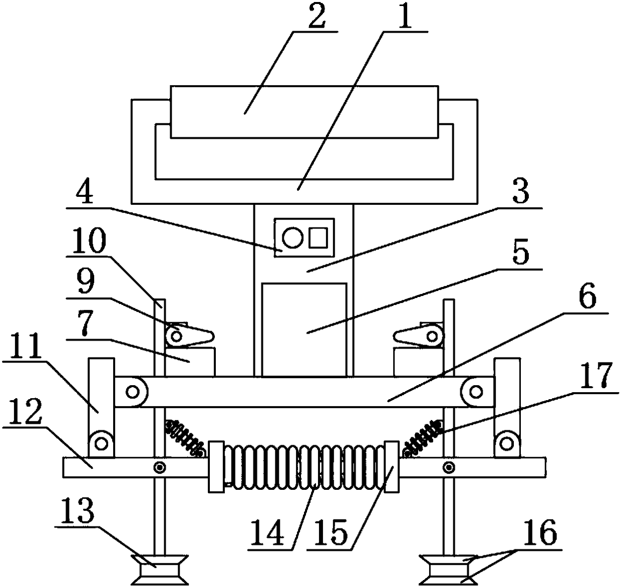
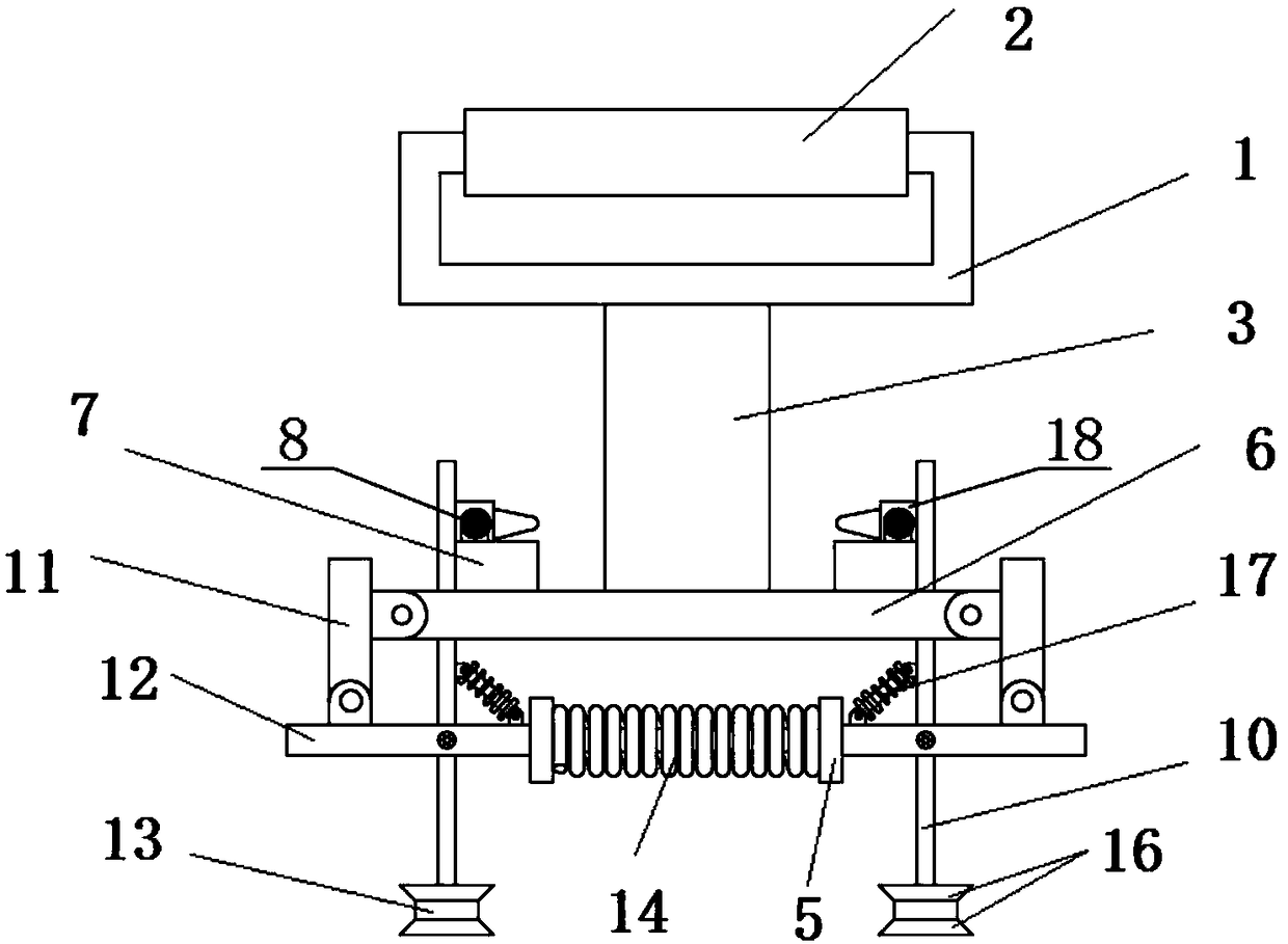
[0027] see Figure 1-5 , in one embodiment, a glass processing clamping device, including a handle 1, a support column 3, a support plate 6, a motor 8, a fixed bracket 10 and a first telescopic rod 12, the middle part of the lower surface of the handle 1 is fixedly connected There is a support column 3, a controller 4 is fixedly connected to one side of the support column 3 close to the top, a storage battery 5 is arranged below the controller 4, and a support...


PUM


Abstract

The invention discloses a glass processing clamping device which comprises a handle, a supporting column, a supporting plate, motors, fixed supports and a first telescopic rod. The middle of the firsttelescopic rod is in sleeved connection with a spring. The two ends of the spring are fixedly connected with limiting rings. The left side and the right side of the first telescopic rod are rotationally connected with the fixed supports through pin shafts. One end of each fixed support is rotationally connected with one end of a second telescopic rod through a lifting lug and a rotating shaft. The other end of each second telescopic rod is rotationally connected with the first telescopic rod through a rotating shaft and a lifting lug. According to the glass processing clamping device, throughthe cooperation function of the spring and the telescopic rods, traditional supporting rod clamping is replaced by the clamping manner, glass can be clamped more flexibly and conveniently, and therefore glass of different sizes can be clamped, and the work efficiency of glass clamping is improved.

Description

technical field [0001] The invention relates to the technical field of industrial processing equipment, in particular to a clamping device for glass processing. Background technique [0002] During the coating process, the panel glass to be processed needs to be transported to the coating equipment through the corresponding transmission line. After the coating operation is completed, the coated panel glass is transported out, and the equipment for transmitting the panel glass is in the transmission panel glass. During the process, the panel glass needs to be grasped and transported one by one. Since the surface of the panel glass cannot be polluted during the coating of the panel glass, this puts forward higher requirements for the panel glass grasping operation. However, the existing panel glass grasping The mechanism cannot adapt to this requirement, which will easily cause pollution and slow speed and low efficiency during the grabbing process of the panel glass, and even...

Claims


Application Information

Patent Timeline
Patent Type & Authority Applications(China)
IPC IPC(8): B25J15/02B25J15/00
CPCB25J15/00B25J15/0253
Inventor 兰天龙江
Owner 江西昌浩实业有限公司
Learn More