Adjustable wireless fixed point monitoring device

A monitoring equipment and adjustable technology, applied in electrical equipment structural parts, TVs, color TVs, etc., can solve the problems of limited monitoring range of monitoring equipment, damage to the beauty of walls, damage to internal components, etc., to increase stability and resistance. The effect of wind resistance, prolonging service life and easy fixed installation

Pending Publication Date: 2018-08-24
苏州柯谱瑞欣通信科技有限公司
View PDF0 Cites 3 Cited by
  • Summary
  • Abstract
  • Description
  • Claims
  • Application Information

AI Technical Summary

Problems solved by technology

[0002] Wireless fixed-point monitoring equipment, also known as computer cameras, computer eyes, electronic eyes, etc., is a video input device that is widely used in video conferencing, telemedicine and real-time monitoring. Ordinary people can also communicate with each other through the network through the camera. Conversation and communication with video and sound. The existing monitoring equipment sold in the market is generally wired transmission. For those places that have not been renovated, the wiring ducts can be reserved in advance, but for the families that have completed the decoration, they can not be left. Lines and pipes, and then installing lines will damage the beauty of the wall. At the same time, there are blind spots in the existing cameras when they are in use, and the use effect cannot be guaranteed 100%. In addition, the existing monitoring equipment is not stable enough when fixed, and the monitoring equipment monitors when in use. The limited range makes the monitoring equipment not practical enough, and the heat dissipation effect of the existing monitoring equipment is not obvious enough, and it is easy to cause internal device damage due to excessive temperature

Method used


Image

  • Adjustable wireless fixed point monitoring device
  • Adjustable wireless fixed point monitoring device
  • Adjustable wireless fixed point monitoring device

Examples


Embodiment Construction

[0015] The following will clearly and completely describe the technical solutions in the embodiments of the present invention with reference to the accompanying drawings in the embodiments of the present invention. Obviously, the described embodiments are only some, not all, embodiments of the present invention. Based on the embodiments of the present invention, all other embodiments obtained by persons of ordinary skill in the art without making creative efforts belong to the protection scope of the present invention.

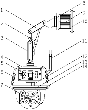
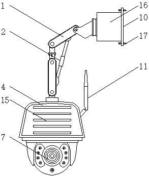
[0016] see Figure 1-3 , an embodiment provided by the present invention: an adjustable wireless fixed-point monitoring device, including a main body 4, a camera 7 and a connecting plate 10, a housing 16 is installed on one side of the connecting plate 10, and the inside of the housing 16 is installed There is a motor 9, and the model of the motor 9 can be Y90S-2. Bolts 17 are evenly arranged on the edge of the top of the connecting plate 10, which is convenie...


PUM


Abstract

The invention discloses an adjustable wireless fixed point monitoring device comprising a main body, a camera and a connecting plate, wherein a shell is installed on one side of the connecting plate,a motor is installed in the shell, a rotating base is installed on an output end of the motor through a rotating shaft, a first mechanical arm is installed on one side of the rotating base away from the shell, a second mechanical arm is installed on end of the first mechanical arm through a hydraulic expansion link, the main body is installed on one side of the second mechanical arm away from thefirst mechanical arm, the circuit board is installed on the top end in the main body, and an image receiving module is installed at one end of the circuit board. The adjustable wireless fixed point monitoring device disclosed by the invention is provided with the motor, the rotating base, the first mechanical arm and the second mechanical arm, so that the device can conveniently rotate to adjust the monitoring angle in a monitoring process, in this way, the monitoring range is wide, the adjustable manner of the device is embodied, accordingly the adjustable wireless fixed point monitoring device is suitable for many occasions and is practical.

Description

technical field [0001] The invention relates to the technical field of monitoring equipment, in particular to an adjustable wireless fixed-point monitoring equipment. Background technique [0002] Wireless fixed-point monitoring equipment, also known as computer cameras, computer eyes, electronic eyes, etc., is a video input device that is widely used in video conferencing, telemedicine and real-time monitoring. Ordinary people can also communicate with each other through the network through the camera. Conversation and communication with video and sound. The existing monitoring equipment sold in the market is generally wired transmission. For those places that have not been renovated, the wiring pipeline can be reserved in advance, but for the family that has completed the decoration, it is not left. Lines and pipes, and then installing lines will damage the beauty of the wall. At the same time, there are blind spots in the existing cameras when they are in use, and the use...

Claims


Application Information

Patent Timeline
Patent Type & Authority Applications(China)
IPC IPC(8): H04N5/225H04N5/232H04N7/18H05K7/20G03B17/08
CPCH04N7/18H05K7/20409G03B17/08H04N23/50H04N23/60
Inventor 孙斌朱王陈
Owner 苏州柯谱瑞欣通信科技有限公司
Why Eureka
Try Eureka