
Single stator framework, chain type motor stator and motor

A technology of stator frame and single body, which is applied in the fields of stator frame body, chain motor stator, and motor. It can solve the problems of large temperature rise of the motor stator, generation safety, and unreliable insulation performance, so as to increase the heat dissipation area and effectively The effect of control

Pending Publication Date: 2018-08-28
ZHUHAI KAIBANG MOTOR MFR +1
View PDF8 Cites 2 Cited by
  • Summary
  • Abstract
  • Description
  • Claims
  • Application Information

AI Technical Summary

Problems solved by technology

However, this traditional method not only consumes a lot of manpower and time, but also leads to poor insulation effect due to improper operation of manual slot insulation, resulting in potential safety hazards, that is, this traditional method has low production efficiency and unreliable insulation performance.
In order to overcome the above-mentioned problems of this traditional method, the current electronic insulation frame is used, but the existing motor stator with the insulation frame has poor heat dissipation, which leads to a large temperature rise problem in the stator of this kind of motor, and there is also a stator integral When the winding is round, the windings are easy to loose, the thermal protector is difficult to fix, and the winding of the stator frame is easy to damage the wires. In addition, for the stator insulating frame commonly used at present, it is necessary to ensure the clamping of the stator insulating frame to the upper and lower sides of the stator core. As a result, the structure of the upper frame and the lower frame of the current stator frame are designed differently, especially at the junction of the upper and lower frames, which will lead to the need for different molds for the upper frame and the lower frame during the production process of the stator frame. , it can be seen that its manufacturing cost is relatively high, and at the same time, the stator skeleton has poor versatility due to the difference in structural design of the upper and lower skeletons that are molded separately.

Method used


Image

  • Single stator framework, chain type motor stator and motor
  • Single stator framework, chain type motor stator and motor
  • Single stator framework, chain type motor stator and motor

Examples


Embodiment Construction

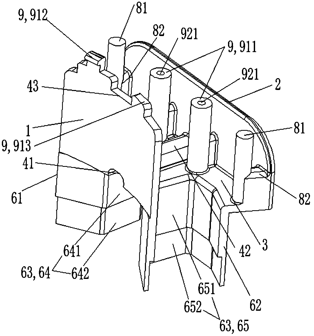
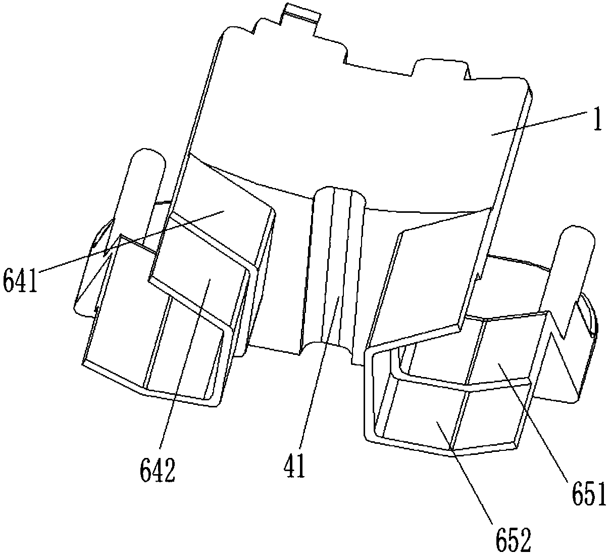
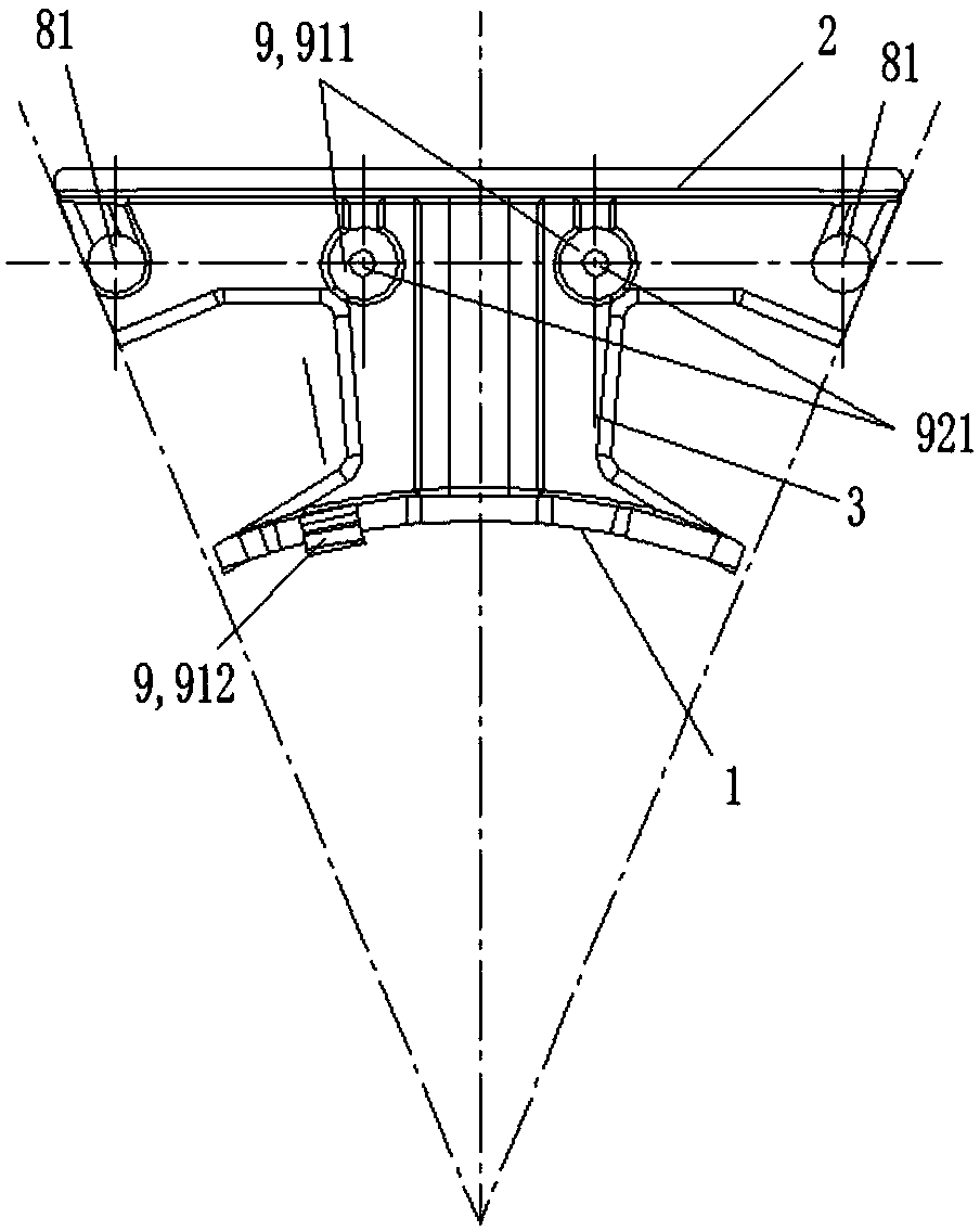
[0035] see Figure 1 to Figure 6 As shown, according to the embodiment of the present invention, a single stator skeleton is provided, including an inner ring wall 1, an outer ring wall 2, and a connecting wall 3 between the inner ring wall 1 and the outer ring wall 2. The ring wall 2 is disposed on the end surface of the stator core 104 , and the end surface of the stator core 104 is partially exposed on the outer peripheral side of the outer ring wall 2 . In this technical solution, since the outer ring wall 2 exposes the end face of the stator core 104 on the outer peripheral side of the outer ring wall 2, when the stator skeleton is assembled with the stator core 104 The exposed heat dissipation surface 105 is formed on the upper and lower end surfaces of the outer wall of the stator core 104. This method avoids that the stator core 104 in the prior art is embedded in the outer ring wall with a curved surface. , the problem of excessive temperature rise caused by the smal...


PUM


Abstract

The invention provides a single stator framework, a chain type motor stator and a motor. The single stator framework comprises an inner ring wall, an outer ring wall and a connecting wall positioned between the inner ring wall and the outer ring wall; and the outer ring wall is arranged on the end plane of the stator iron core, and the end plane of the stator iron core is partially exposed from the peripheral side of the outer ring wall. According to the single stator framework, the chain type motor stator and the motor provided by the invention, the matching area between the stator iron coreand the stator framework can be reduced, the heat dissipation area of the stator iron core can be enlarged, heat dissipation of the motor stator can be better facilitated, and temperature rise of themotor is lowered.

Description

technical field [0001] The invention belongs to the technical field of motors, and in particular relates to a single stator frame, a chain-type motor stator and a motor. Background technique [0002] In the traditional motor stator production process, the stator frame is generally not used. At this time, before the stator winding is embedded in the stator core, it is necessary to manually insert the insulating material into the insulation groove of the stator core for insulation treatment, so as to improve the stator winding and stator iron core. Insulation between cores increases safety. However, this traditional method not only consumes a lot of manpower and time, but also leads to poor insulation effect due to improper operation of artificial slot insulation, resulting in potential safety hazards, that is, the traditional method has low production efficiency and unreliable insulation performance. In order to overcome the above-mentioned problems of this traditional metho...

Claims


Application Information

Patent Timeline
Patent Type & Authority Applications(China)
IPC IPC(8): H02K3/32H02K3/38H02K3/50
CPCH02K3/32H02K3/38H02K3/50H02K2203/12
Inventor 姚宇涵曾文志李文宇李庆陈东锁
Owner ZHUHAI KAIBANG MOTOR MFR
Learn More