
Distributed winding flexible transformer by mixed winding of magnetic conductive wire and electrical wire

A distributed winding and flexible transformer technology, applied in the field of transformers, can solve the problems of occupying the space of printed circuit boards, and achieve the effects of flexible overall structure design, good heat dissipation, and reduced copper consumption

Inactive Publication Date: 2011-09-21
XI AN JIAOTONG UNIV
View PDF4 Cites 2 Cited by
  • Summary
  • Abstract
  • Description
  • Claims
  • Application Information

AI Technical Summary

Problems solved by technology

The planar transformer can reduce the power supply volume of the PCB (printed circuit board) circuit, but it is mainly used in the high-frequency switching power supply chopper circuit of hundreds of kHz. The winding and magnetic core of the transformer need to be arranged on the printed circuit board. Occupies some PCB space

Method used


Image

  • Distributed winding flexible transformer by mixed winding of magnetic conductive wire and electrical wire
  • Distributed winding flexible transformer by mixed winding of magnetic conductive wire and electrical wire
  • Distributed winding flexible transformer by mixed winding of magnetic conductive wire and electrical wire

Examples


Embodiment Construction

[0031] The present invention will be described in detail below in conjunction with the accompanying drawings and specific embodiments.

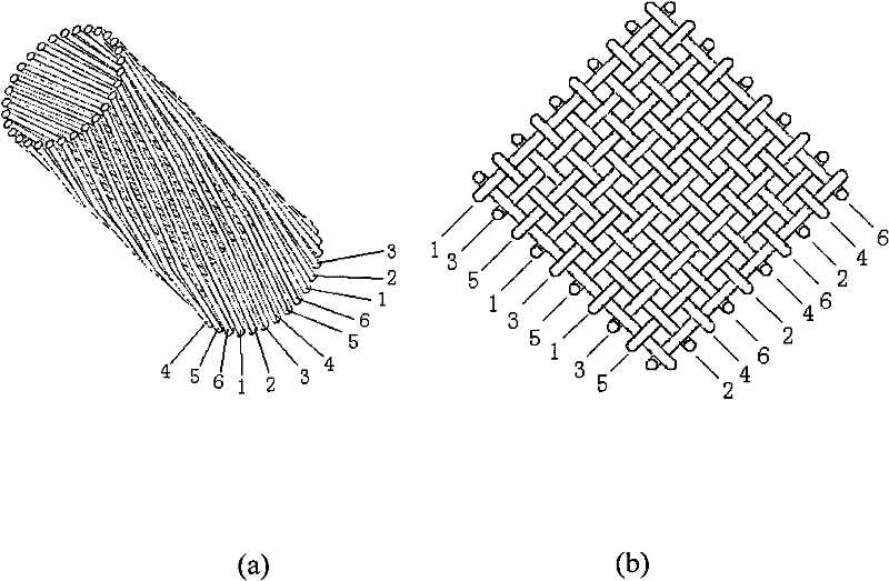
[0032] refer to figure 1 As shown, the coil winding method of the transformer adopts figure 1 (a) Structure shown. The primary winding copper wires of the coil and the secondary winding copper wires are arranged adjacently, that is, copper wires 1, 3, and 5 are primary winding wires, copper wires 2, 4, and 6 are secondary winding wires, and the two adjacent copper wires The wires belong to the primary winding and the secondary winding respectively, and the two separated copper wires belong to the winding of the same phase. The primary winding and the secondary winding are arranged circularly on the surface of the magnetic core in turn. In order to ensure that the coil is fixed on the surface of the magnetic core, the above-mentioned conductive copper wire is helically wound along the surface layer of the magnetic core, that is, the copper w...


PUM


Abstract

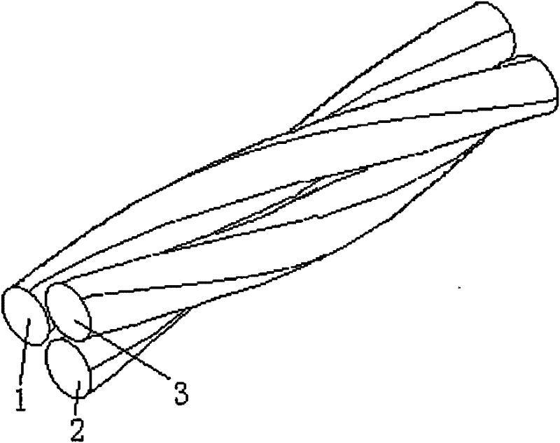
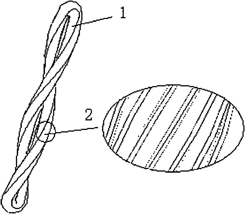
The invention discloses a distributed winding flexible transformer formed by the mixed winding of magnetic conductive leads and electric leads. A magnetic core of the transformer adopts a stranded wire structure or a magnetic strip layered structure, and each magnetic conductive lead is insulated from the magnetic strip. A coil of the transformer adopts the distributed winding structure; the number of winding layers of the coil is much less than that of a traditional winding transformer, and the coil windings are uniformly distributed along the length direction of the magnetic core. The winding method of a primary winding and a secondary winding can coil in screw way along a surface of the magnetic core, and also can cross in two-dimensional grid structure along the surface of the magnetic core. A warp thread and a weft of the two-dimensional grid are a primary winding lead and a secondary winding lead respectively. The integral structure of the transformer can adopt a duplex or triple helix structure, as well as a disk-like structure or others. The transformer is mainly used for a signal transformer and a low power transformer working at low frequency, and the transformer has themain advantages of excellent heat emission and flexible design of the integral structure.

Description

technical field [0001] The invention belongs to the field of transformers, and relates to a distributed winding flexible transformer in which magnetic conducting wires and conducting wires are mixedly wound. Background technique [0002] Transformer is an electromagnetic device widely used in circuit design. Its main function is to transmit energy and signal. The performance of transformer directly affects the working quality of the circuit, and also reflects the level of circuit design to a large extent. According to the different uses of the transformer, its structure and electrical parameters are also very different, showing the characteristics of diversity. At present, the traditional wire-wound transformer for energy transfer and power conversion in circuit design is being replaced by switching power supply with power electronic switch as the main device to reduce the volume and improve the flexibility of power supply design. Although the development and application of...

Claims


Application Information

Patent Timeline
Patent Type & Authority Patents(China)
IPC IPC(8): H01F30/06H01F27/24H01F27/28H01F41/02H01F41/04H01F41/06H01F41/071
Inventor 娄建勇梁得亮陈以通
Owner XI AN JIAOTONG UNIV
Learn More