An AC bus magnetically coupled energy harvesting device and method

A technology for energy harvesting devices and AC busbars, applied in the direction of preventing/reducing unwanted electric/magnetic influences, inductors, electrical components, etc., can solve the problems of affecting voltage insulation, inconvenient installation, and complicated installation, etc., to reduce conduction Magnetic effect, simple and convenient use, high energy harvesting efficiency

Active Publication Date: 2019-10-15
CHANGSHU SWITCHGEAR MFG CO LTD (FORMER CHANGSHU SWITCHGEAR PLANT)
View PDF6 Cites 0 Cited by
  • Summary
  • Abstract
  • Description
  • Claims
  • Application Information

AI Technical Summary

Problems solved by technology

However, battery power supply requires battery replacement and maintenance; wireless power transmission power supply requires correspondence between the transmitting side and the receiving side, the installation is complicated, and it is difficult to apply to complex electrical wiring environments; the core-through energy harvesting CT needs to be worn on the current-carrying bus. The installation is complicated, and it takes up a lot of space, which affects the voltage insulation and is difficult to apply to compact applications.
[0004] Therefore, the main problems of the existing above-mentioned technologies are that they are bulky, inconvenient to install or require maintenance.
If the volume is reduced, the energy harvesting power is too small to meet the electric energy demand of the electronic circuit

Method used


Image

  • An AC bus magnetically coupled energy harvesting device and method
  • An AC bus magnetically coupled energy harvesting device and method
  • An AC bus magnetically coupled energy harvesting device and method

Examples


Embodiment 1

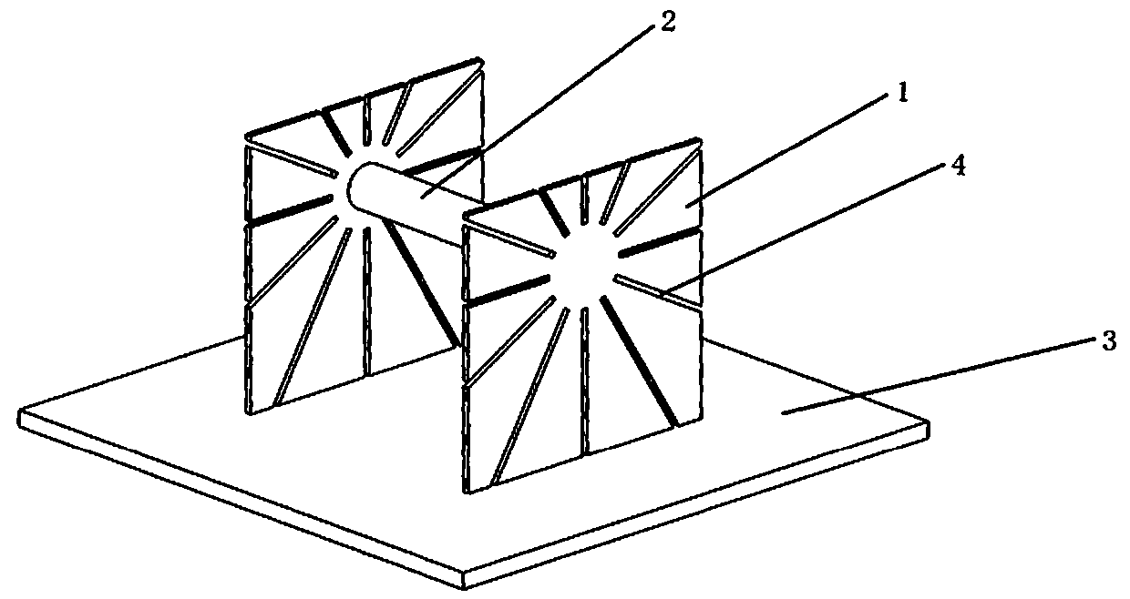
[0044] Such as figure 1 As shown, the magnetic column is a cylinder, and the radius of the longitudinal section is equal from the middle to both sides of the magnetic column.

Embodiment 2

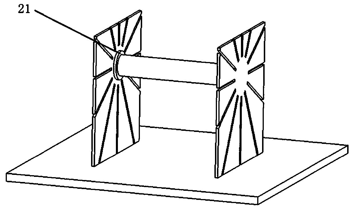
[0046] Such as figure 2 As shown, the magnetic column is a cylinder with a circular longitudinal section, and the radius of the section is smaller in the middle and larger at both ends. For example, the two ends 21 in contact with the magnetically permeable side plates have a larger area, and the middle part has a smaller area.

Embodiment 3

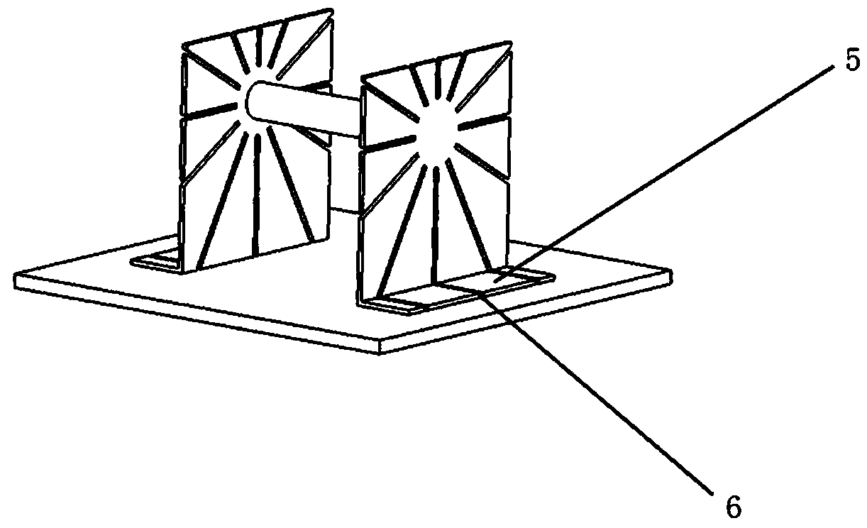
[0048] Such as image 3 As shown, on the basis of Embodiment 1, the bottom end of the magnetically permeable side plate is provided with two bottom plates 5 connected thereto. Adding a base plate to the magnetically permeable side plate can enhance the magnetic gathering ability of the magnetically permeable side plate, thereby increasing the output power of the entire magnetic coupling structure. A linear gap 6 is opened on the bottom plate, and the opening direction of the linear gap is consistent with the direction of the magnetic force line of the static magnetic field in the bottom plate under the condition of direct current.


PUM


Abstract

The invention relates to an alternating current bus magnetic coupling energy extracting device and method. The device comprises a pair of magnetic conductive side plates, a magnetic pillar and a winding, wherein the magnetic conductive side plates are arranged at the upper portion of an alternating current current-carrying busbar, the magnetic pillar is arranged between the magnetic conductive side plates and the two sides of the magnetic pillar are fixedly connected to the inner side face of the corresponding magnetic conductive side plate respectively, and the winding is arranged on the magnetic pillar in a winding mode. Alternating current magnetic flow generated by attracting the current of the alternating current busbar through the magnetic conductive side plates is centered through the magnetic pillar, and a voltage is output through winding induction. Through the alternating current bus magnetic coupling energy extracting device and method, the energy extracting device of electric energy can be directly obtained through magnetic coupling from the alternating current current-carrying busbar, it is only required that the device is placed at the upper portion of the busbar, enough electric energy can be obtained from the alternating current current-carrying busbar for supplying electricity for an electronic circuit, and the device is simple and convenient to use, small in size, free of maintenance and high in energy extracting efficiency.

Description

technical field [0001] The invention relates to an AC bus magnetic coupling energy harvesting device and method. Background technique [0002] In order to detect the voltage, current, temperature and other information of the AC current-carrying busbar and transmit this information wirelessly, it is necessary to supply power to the detection and wireless transmission electronic circuits. Therefore, there is a need for an energy harvesting device that is small in size, maintenance-free, and easy to install, and can directly obtain electric energy from the current-carrying busbar. [0003] In order to obtain electric energy from the AC current-carrying busbar to supply power to the detection electronic circuit, existing methods use battery power supply, wireless power transmission power supply or through-the-core energy harvesting CT power supply. However, battery power supply requires battery replacement and maintenance; wireless power transmission power supply requires corre...

Claims


Application Information

Patent Timeline
Patent Type & Authority Patents(China)
IPC IPC(8): H01F38/14H01F27/34
Inventor 陈为柳百毅
Owner CHANGSHU SWITCHGEAR MFG CO LTD (FORMER CHANGSHU SWITCHGEAR PLANT)
Why Eureka
Try Eureka