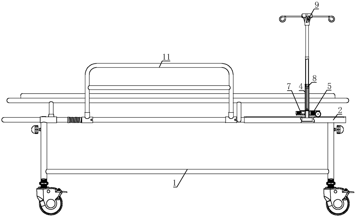
Patient transfer cart with infusion support auto-adjusting function
An automatic adjustment and infusion stand technology, which is applied in the direction of hospital beds, stretchers, medical transportation, etc., can solve the problem that the position of the patient transfer trolley cannot be adjusted, and achieve the effect of avoiding blood return and convenient and precise adjustment
- Summary
- Abstract
- Description
- Claims
- Application Information
AI Technical Summary
Problems solved by technology
Method used
Image
Examples
Embodiment 1
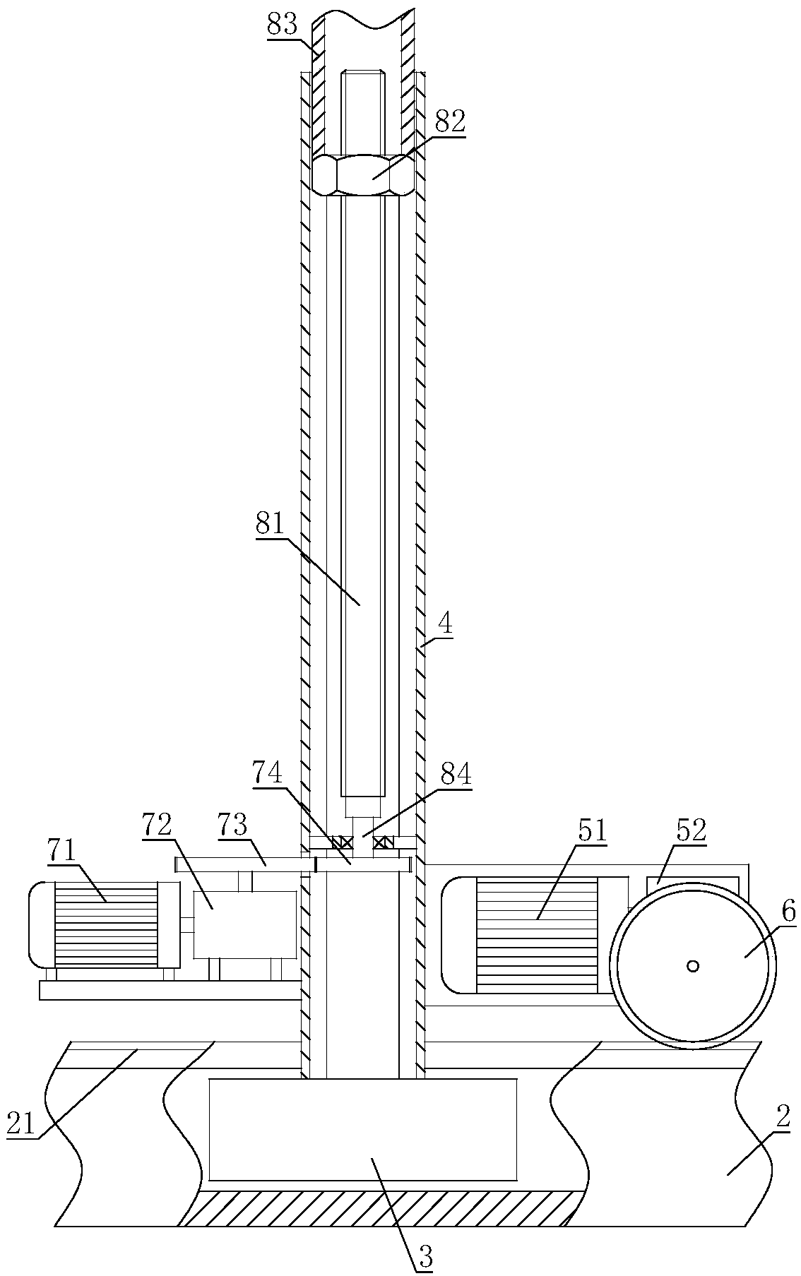
[0024] The patient transfer trolley with automatic adjustment of the infusion stand includes a main body 1 of the trolley; the main body 1 of the trolley is connected with a chute 2, and a slider 3 is set inside the chute 2, and a polygonal tube 4 is connected to the slider 3 , the polygonal tube 4 is equipped with a traversing drive mechanism 5, the output shaft of the traversing drive mechanism 5 is connected with a traversing gear 6, the chute 2 is provided with a rack 21, and the traversing gear 6 meshes with the rack 21; the polygonal tube 4 is also equipped with a lifting drive mechanism 7, the output shaft of the lifting drive mechanism 7 is connected with a lead screw nut mechanism 8, the lead screw nut mechanism 8 is sleeved in the polygonal tube 4, and the other end of the lead screw nut mechanism 8 is connected with an infusion stand 9.
[0025] When the traversing drive mechanism 5 of the present invention drives the traversing gear 6 to rotate, the traversing gear...
Embodiment 2
[0027] On the basis of Embodiment 1, the traversing drive mechanism 5 includes a traversing motor 51, the output shaft of the traversing motor 51 is connected with a traversing reducer 52, and the traversing motor 51 and the traversing reducer 52 are connected to the polygonal tube 4 is fixedly connected, and the traverse gear 6 is connected to the output shaft of the traverse reducer 52.
[0028] The traverse motor 51 can drive the traverse reducer 52 to rotate, and the traverse reducer 52 drives the traverse gear 6 to rotate. Then, by controlling the rotation of the traverse motor 51, the moving direction of the transfusion stand 9 can be controlled; by controlling the starting time of the traverse motor 51, the traverse distance of the transfusion stand 9 can be precisely adjusted.
Embodiment 3
[0030] On the basis of Embodiment 1 or Embodiment 2, the lead screw nut mechanism 8 includes a lead screw 81, the lead screw 81 is threadedly connected with a nut 82, the nut 82 is sleeved in the polygonal tube 4, and the other end of the nut 82 is connected with a Lifting tube 83, infusion stand 9 is fixed with lifting tube 83; One end of leading screw 81 is connected with rotating shaft 84, and rotating shaft 84 is connected in the polygonal pipe 4 by bearing, and the other end of rotating shaft 84 is connected with the output shaft of lifting drive mechanism 7.
[0031] When the lifting drive mechanism 7 drives the screw 81 to rotate, the nut 82 is linearly lifted due to being restricted by the polygonal tube 4, so that the nut 82 can push the lifting tube 83 and the infusion stand 9 to lift. The screw nut mechanism 7 has a definite transmission ratio, which is convenient for precise adjustment of the height of the infusion bag.
PUM
 Abstract
Description
Claims
Application Information
 - R&D
- Intellectual Property
- Life Sciences
- Materials
- Tech Scout
- Unparalleled Data Quality
- Higher Quality Content
- 60% Fewer Hallucinations
Browse by: Latest US Patents, China's latest patents, Technical Efficacy Thesaurus, Application Domain, Technology Topic, Popular Technical Reports.
© 2025 PatSnap. All rights reserved.Legal|Privacy policy|Modern Slavery Act Transparency Statement|Sitemap|About US| Contact US: help@patsnap.com


