

Display screen capable of adjusting position conveniently
A display screen, a convenient technology, applied in the field of display screens, can solve the problems of inability to adjust the horizontal position and height, etc., and achieve the effect of convenient operation and use
- Summary
- Abstract
- Description
- Claims
- Application Information
AI Technical Summary
Problems solved by technology
Method used
Image

Examples
Embodiment 1
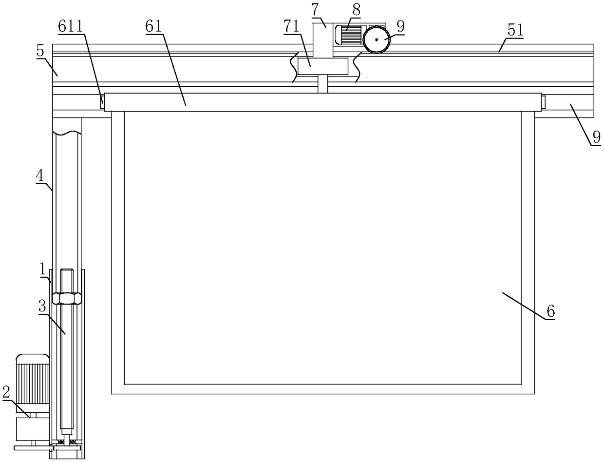
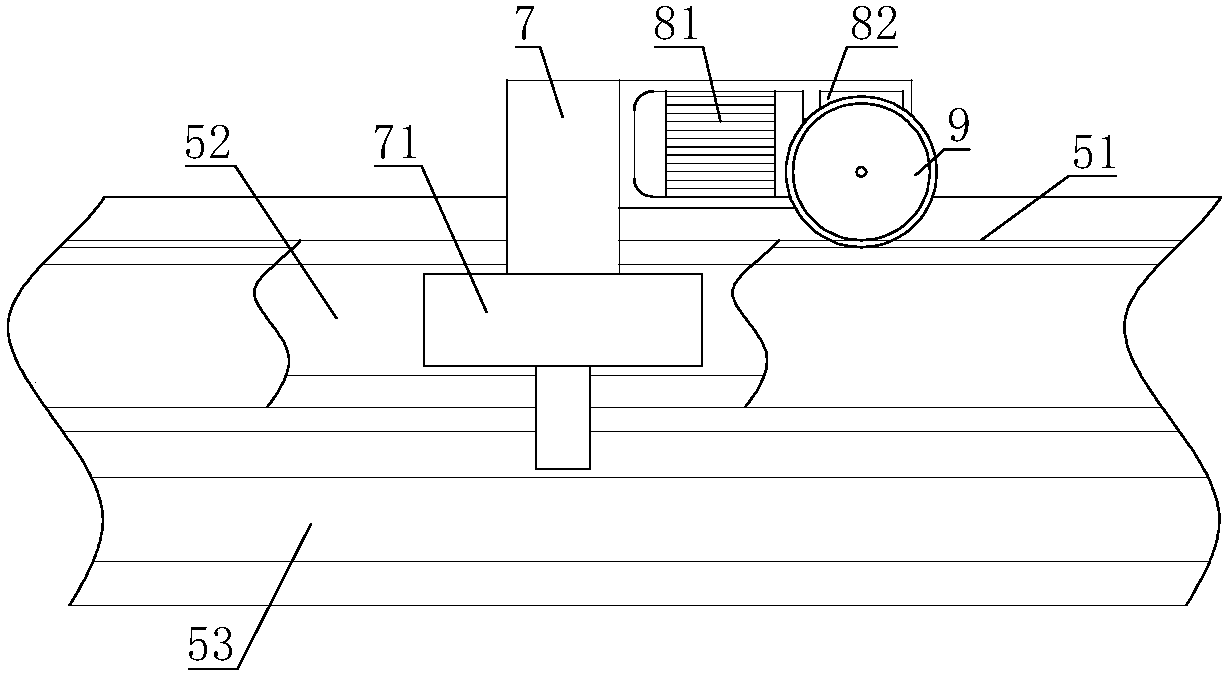
[0028] The display screen with convenient position adjustment includes a polygonal tube 1, a lifting drive mechanism 2 is installed inside the polygonal tube 1, the output shaft of the lifting drive mechanism 2 is connected with a screw nut mechanism 3, and the screw nut mechanism 3 is sleeved on the polygonal tube 1 Inside, the other end of the lead screw and nut mechanism 3 is connected with the lifting tube 4, and the other end of the lifting tube 4 is connected with the horizontal frame 5, and the horizontal frame 5 is provided with a rack 51; An upper frame 61 is connected, and a traverse frame 7 is fixed on the upper frame 61. A traverse drive mechanism 8 is installed on the traverse frame 7. The output shaft of the traverse drive mechanism 8 is connected with a gear 9, and the gear 9 meshes with the rack 51. .
[0029] The lifting drive mechanism 2 of the present invention can drive the lead screw and nut mechanism 3 to move, then the lead screw and nut mechanism 3 can ...
Embodiment 2
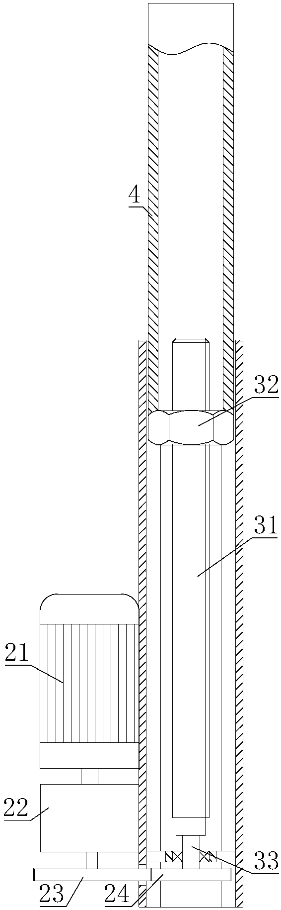
[0031] On the basis of Embodiment 1, the lead screw nut mechanism 3 includes a lead screw 31, the lead screw 31 is threadedly connected with a nut 32, the nut 32 is sleeved in the polygonal tube 1, and the other end of the nut 32 is connected with the lifting tube 4; One end of the leading screw 31 is connected with a rotating shaft 33, the rotating shaft 33 is connected in the polygonal tube 1 through a bearing, and the lifting drive mechanism 2 of the rotating shaft 33 is connected.
[0032] When the lifting drive mechanism 2 drives the rotating shaft 33 to rotate, the leading screw 31 rotates accordingly. Since the polygonal tube 1 can limit the rotation of the nut 32, the nut 32 can move linearly in the polygonal tube 1. Therefore, the nut 32 can drive the lifting pipe 4 to move, and the main body of the display screen 6 can rise and fall accordingly.
Embodiment 3
[0034] On the basis of Embodiment 1 or Embodiment 2, the lifting drive mechanism 2 includes a lifting motor 21, the output shaft of the lifting motor 21 is connected with a lifting reducer 22, and the lifting motor 21 and the lifting reducer 22 are fixed on the polygonal tube 1 Above, the output shaft of the lift reducer 22 is connected with a driving gear 23 , the driving gear 23 is meshed with a driven gear 24 , and the driven gear 24 is connected with the screw nut mechanism 3 .
[0035] The lifting motor 21 can drive the lifting reducer 22 to move, the lifting reducer 22 drives the driving gear 23 to rotate, and the driven gear 24 drives the leading screw and nut mechanism 3 to move. The direction of movement of the display screen main body 6 can be controlled by controlling the steering of the lifting motor 21, and the movement distance of the display screen main body 6 can be precisely controlled by controlling the action time of the lifting motor 21, which is convenient ...
PUM
 Abstract
Description
Claims
Application Information