
A method for reusing residual energy of power-assisted bicycle brakes

A technology for assisting bicycles and recycling, applied in bicycle accessories, bicycle brakes, vehicle parts, etc., can solve the problem that the collection efficiency of pneumatic bicycles cannot be adjusted in real time, and achieve the effect of good braking effect, high compression efficiency, and increased inertia.

Active Publication Date: 2020-09-04
ANHUI POLYTECHNIC UNIV
View PDF2 Cites 0 Cited by
  • Summary
  • Abstract
  • Description
  • Claims
  • Application Information

AI Technical Summary

Problems solved by technology

[0006] The purpose of the present invention is to solve the problem that the collection efficiency of the existing pneumatic bicycles cannot be adjusted in real time, and to provide a method for reusing the residual energy of the brakes of the power-assisted bicycle. Output pneumatic power assist; when the brake mechanism is pressed for braking, the power assist unit stops outputting power, and the power recovery unit starts to recover power, the compression cylinder of the power recovery unit compresses the gas, and the compressed gas is transported to the energy storage tank through the pipeline. The brake mechanism adjusts the compression ratio of the compression cylinder, and controls the braking strength by controlling the compression ratio of the compression cylinder, which is not only convenient for assisting, but also convenient for adjusting the power recovery intensity to adjust the braking effect

Method used


Image

  • A method for reusing residual energy of power-assisted bicycle brakes
  • A method for reusing residual energy of power-assisted bicycle brakes
  • A method for reusing residual energy of power-assisted bicycle brakes

Examples


Embodiment 1

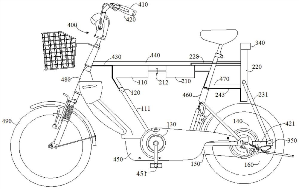
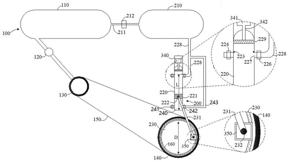
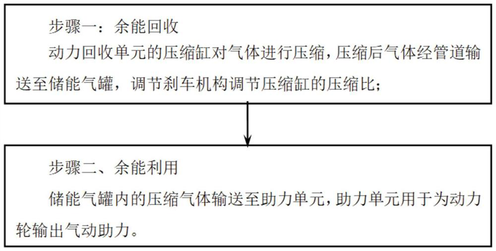
[0040] Refer to attached figure 1 , figure 2 and image 3 As shown, a method for reusing residual energy of a power-assisted bicycle brake in this embodiment, the method includes the following steps,

[0041] Step 1. Recycling surplus energy

[0042] When the brake mechanism 420 is pressed for braking, the booster unit 100 stops outputting power, and the power recovery unit 200 starts to recover power. The compression cylinder 220 of the power recovery unit 200 compresses the gas, and the compressed gas is transported to the energy storage through the gas outlet pipe 228 of the compression cylinder. The gas tank 210 adjusts the compression ratio of the compression cylinder 220 by adjusting the brake mechanism 420, and controls the braking strength by controlling the compression ratio of the compression cylinder 220;

[0043] Step 2. Utilization of surplus energy

[0044] The compressed gas in the energy storage tank 210 is sent to the booster unit 100 , and the booster un...


PUM


Abstract

The invention discloses a recycling method for boosting-bicycle braking surplus energy, and belongs to the field of pneumatic bicycles. The recycling method includes the steps of 1, surplus energy recovery, wherein when a braking mechanism is pressed for braking, a boosting unit stops to output power, a power recovery unit starts to recover power, a compression cylinder of the power recovery unitcompresses gas, compressed gas is delivered to an energy storage gas tank through a pipe, the compression ratio of the compression cylinder is adjusted by adjusting the braking mechanism, and the braking strength is controlled by controlling the compression ratio of the compression cylinder; 2, surplus energy using, wherein the compressed gas in the energy storage gas tank is delivered to the boosting unit, and the boosting unit is used for outputting pneumatic boost for wheels. According to the recycling method for the boosting-bicycle braking surplus energy, boosting is conveniently carriedout, and the lower recycling strength is also conveniently adjusted to adjust the braking effect.

Description

technical field [0001] The invention belongs to the field of pneumatic bicycles, and in particular relates to a method for reusing residual braking energy of assisting bicycles. Background technique [0002] With the success of electric mopeds. A variety of new, energy-saving and environmentally friendly mopeds have emerged in response to the market, such as solar mopeds and pneumatic mopeds, but most of them are still in the research stage due to the immaturity of related technologies. Some related patents have already appeared. There are reports of related prototypes abroad, but they have not been sold on the market. It is believed that the new moped will face the market soon along with the development of technology and related personnel. The pneumatic moped that utilizes non-toxic, harmless and low-cost compressed air as a power source has a great competitive advantage. [0003] After retrieval, the name of the invention is: environment-friendly self-inflating pneumat...

Claims


Application Information

Patent Timeline
Patent Type & Authority Patents(China)
IPC IPC(8): B62M6/00B62L1/00B60T1/10
CPCB60T1/10B62L1/00B62M6/00
Inventor 徐振法王银凤梁利东谢正好
Owner ANHUI POLYTECHNIC UNIV
Learn More