Floor drain brick and floor drain structure

A technology for floor drain and floor drain cover, which is applied to drainage structures, building structures, waterway systems, etc., can solve the problems of increasing the economic investment in decoration, the overall effect affecting the appearance of decoration, etc., and achieving the effect of facilitating drainage

Pending Publication Date: 2018-09-04
刘洋
View PDF0 Cites 7 Cited by
  • Summary
  • Abstract
  • Description
  • Claims
  • Application Information

AI Technical Summary

Problems solved by technology

The overall effect after installation affects the beauty of the decoration, and at the same time increases the economic investment of the decoration

Method used


Image

  • Floor drain brick and floor drain structure
  • Floor drain brick and floor drain structure
  • Floor drain brick and floor drain structure

Examples


Embodiment

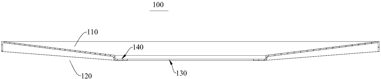
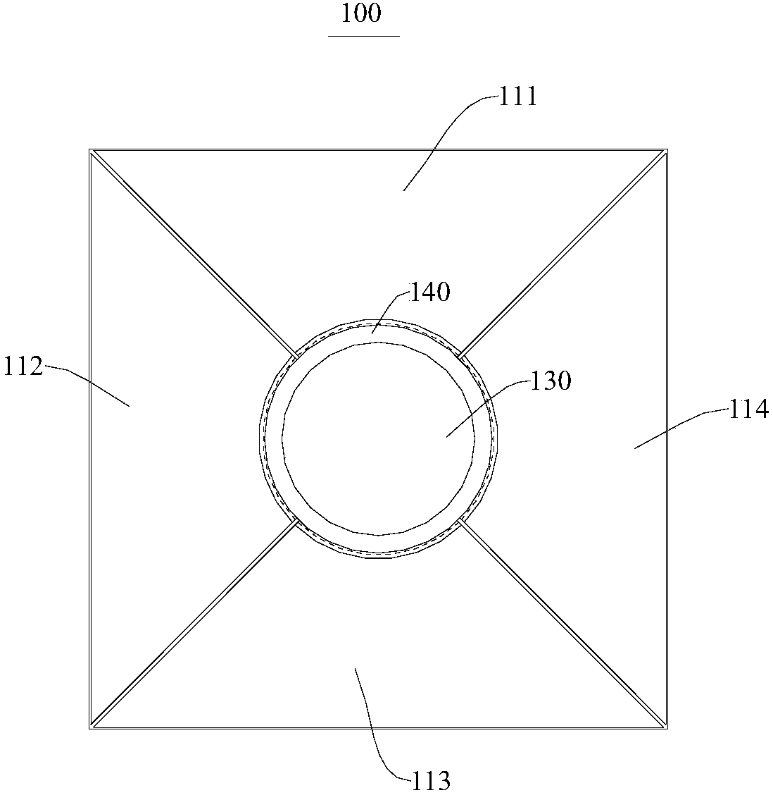
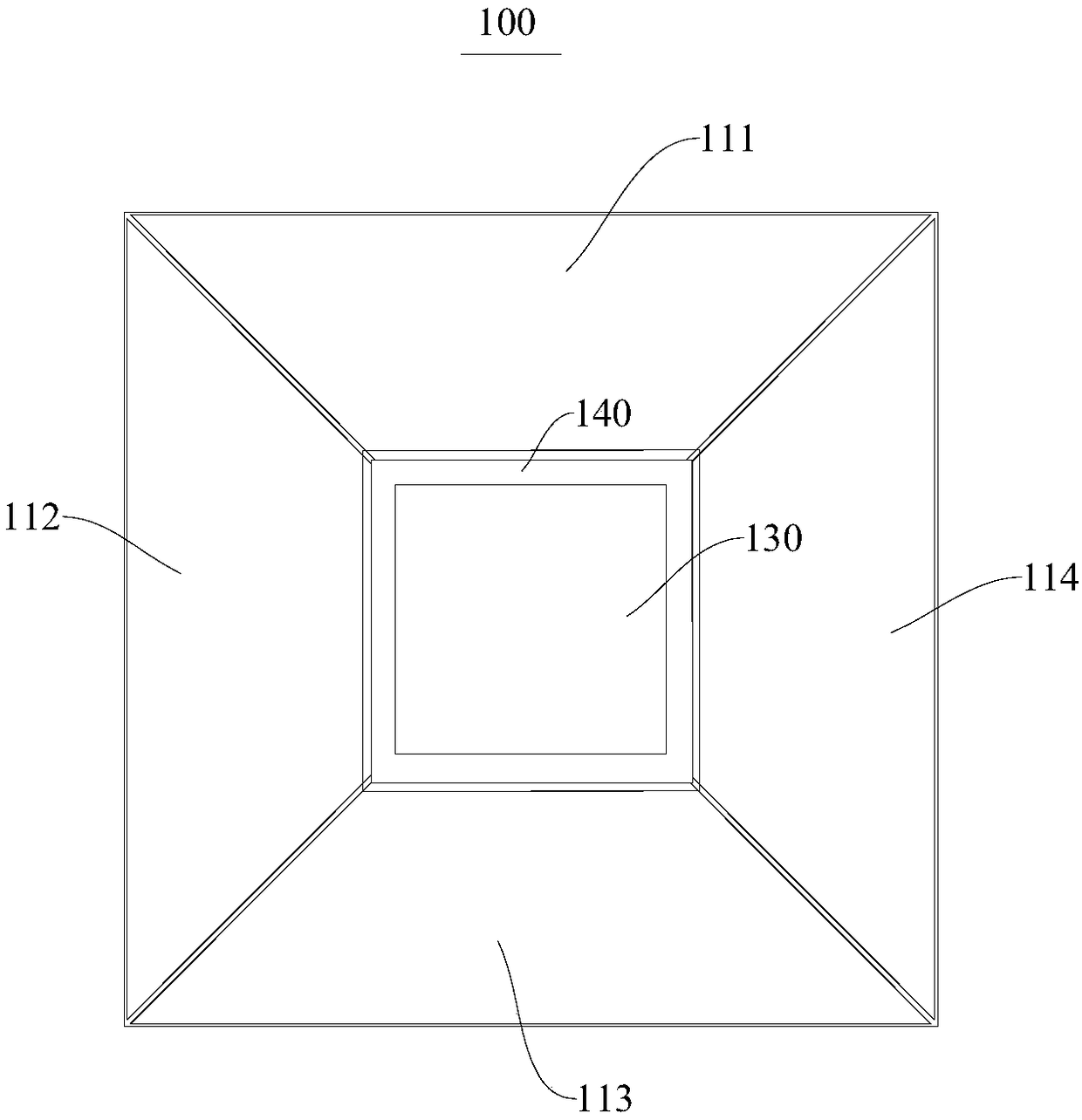
[0042] This embodiment provides a floor drain tile 100, please refer to figure 1 . figure 1 A schematic structural diagram of the floor drain tile 100 from a first viewing angle is shown.

[0043] In this embodiment, the floor drain tile 100 has an integral structure, and the floor drain tile 100 includes opposite first sides 110 and second sides 120 . Such as figure 1 As shown, the floor drain tile 100 includes an upper side and a lower side.

[0044] The floor drain tile 100 is provided with a floor drain installation hole 130 penetrating through the first side 110 and the second side 120, and the periphery of the floor drain installation hole 130 forms an installation step 140, wherein the size of the floor drain installation hole 130 matches the size of the floor drain main body 210. The surface of the first side 110 of the floor drain tile 100 and the installation step 140 have a preset inclination angle. That is, the surface of the first side 110 of the floor drain t...


PUM


Abstract

The invention provides a floor drain brick and a floor drain structure and relates to the technical field of building decoration. The floor drain brick is of an integrated structure and comprises a first side and a second side which are opposite. Floor drain mounting holes penetrating through the first side and the second side are formed in the floor drain brick, and the periphery of each floor drain mounting hole forms a mounting step. Preset inclination angles exist between the surface of the first side of the floor drain brick and the mounting steps. The floor drain brick is of the integrated structure, during floor drain mounting, waste caused by cutting can be avoided, the preset inclination angles exist between the surface of the first side of the floor drain brick and the mounting steps, and thus water can be easily guided to a floor drain from the floor drain brick.

Description

technical field [0001] The invention relates to the technical field of architectural decoration, in particular to a floor drain brick and a floor drain structure. Background technique [0002] In the construction process of installing the floor drain in the current interior decoration, when the floor drain is installed and matched with the floor tiles, the floor tiles need to be cut and assembled due to the installation and drainage requirements of the floor drain. In the process of cutting and assembling, the labor intensity of cutting and splicing the floor tiles is relatively high. The damage rate of the floor tiles during the cutting process is very high, which reduces the utilization rate of the floor tiles, and there are very high skill requirements for the construction personnel during splicing and installation. The overall effect after installation affects the aesthetics of the decoration, and at the same time increases the economic investment of the decoration. Co...

Claims


Application Information

Patent Timeline
Patent Type & Authority Applications(China)
IPC IPC(8): E04F15/02E03F5/04E03F5/06
CPCE04F15/02E03F5/0407E03F5/06
Inventor 刘洋
Owner 刘洋
Why Eureka
Try Eureka