Mold and Stranding Table for Layer Stranded Optical Cable Twisted Head Outlet Cover

A layer-twisted optical cable technology, which is applied in the field of layer-twisted optical cable twist head exit cover molds and stranding tables, can solve the problems affecting the overall stability and instability of the cable tensile performance, and the exit of the twist head exit cover plate. Faster wear and tear of the casing tension and other issues, to avoid different degrees of wear, prolong the wear cycle, reduce the effect of friction cutting

Active Publication Date: 2019-10-25
FENGHUO COMM SCI & TECH CO LTD
View PDF6 Cites 1 Cited by
  • Summary
  • Abstract
  • Description
  • Claims
  • Application Information

AI Technical Summary

Problems solved by technology

[0003] However, in the prior art, the reaming hole on the outlet cover plate of the twisting head is axially the same as the passing hole of the reinforcement member. Before the sleeve pipe comes out from the reaming hole and is twisted with the reinforcement member, the The tube always moves in the same direction as the reinforcement. When the sleeve comes out of the reaming hole and turns to contact the reinforcement, the contact point of the sleeve at the exit of the reaming hole provides this external force for changing direction, which makes the contact point There is not only the supporting force perpendicular to the advancing direction of the casing, but also the frictional force opposite to the advancing direction of the casing. The distance between the mold and the outlet cover of the twisting head is relatively short, and the casing is further rubbed and cut by the contact point at the exit of the twisting hole during the rotation process. The combined action of the above three forces causes the outlet of the exit cover of the twisting head to wear faster And the tension of the sleeve is unstable, and the difference in the degree of wear will be reflected in the length difference of the optical cable sleeve, which will affect the tensile performance of the optical cable and the overall stability of the product

Method used


Image

  • Mold and Stranding Table for Layer Stranded Optical Cable Twisted Head Outlet Cover
  • Mold and Stranding Table for Layer Stranded Optical Cable Twisted Head Outlet Cover
  • Mold and Stranding Table for Layer Stranded Optical Cable Twisted Head Outlet Cover

Examples


Embodiment 1

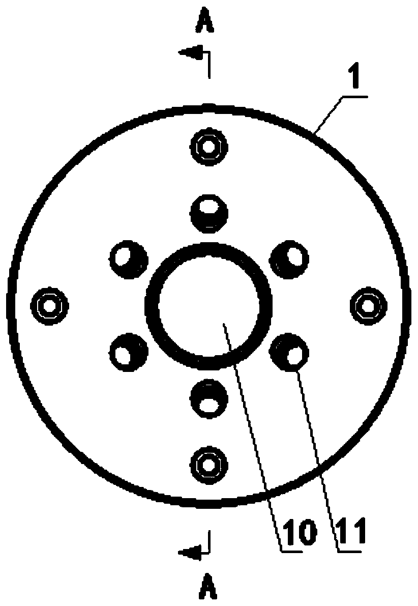
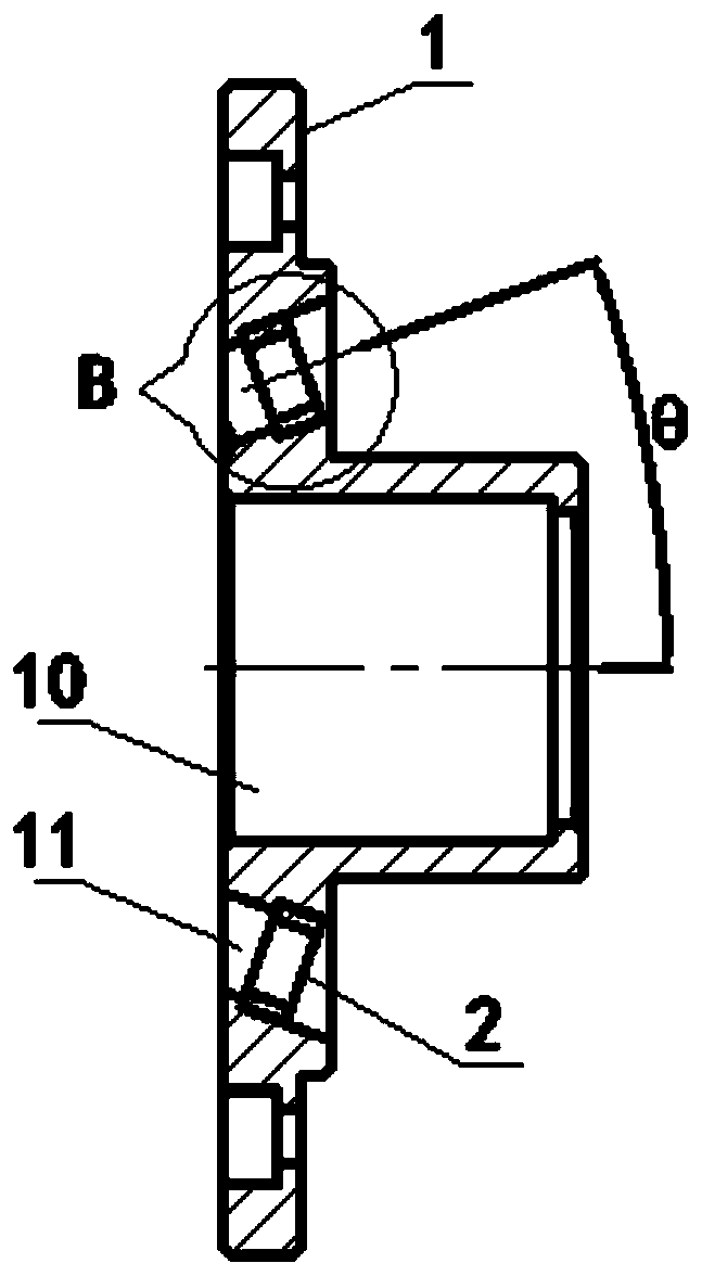
[0033] see figure 1 with figure 2 As shown, the embodiment of the present invention provides a layer-stranded optical cable twist head outlet cover plate mold, which includes a body 1, and the body 1 is provided with a reinforcement passing hole 10 and distributed around the reinforcement passing hole 10. A plurality of reaming holes 11, the number of reaming holes 11 can be set according to actual needs, see figure 1 As shown in , there are 6 reaming holes 11, and they are evenly distributed around the passage hole 10 of the reinforcement member, and the distance between each reaming hole 11 and the passage hole 10 of the reinforcement member is equal; The distance between the entrance end of the hole 11 and the passage hole 10 of the reinforcement is greater than the distance between the exit end and the passage hole 10 of the reinforcement, that is, the reamed hole 11 is an inclined hole, and the reamed hole 11 and The axial angle between the reinforcing member passage h...

Embodiment 2

[0038] see figure 1 with figure 2As shown, the embodiment of the present invention provides a layered type optical cable twist head outlet cover plate mold, which includes a body 1 and a plurality of low friction coefficient backing rings 2, and the body 1 is provided with reinforcement passing holes 10 and distributed in the The reinforcing member passes through a plurality of reaming holes 11 around the hole 10, and the distance between the inlet end of the reaming hole 11 and the reinforcing member passing hole 10 is greater than the distance between its outlet end and the reinforcing member passing hole 10 The low friction coefficient backing ring 2 is embedded in the reamed hole 11, and the reaming hole 11 and the low friction coefficient backing ring 2 located in the reaming hole 11 are arranged coaxially. The low friction coefficient backing ring 2 is arranged in the reamed hole 11, on the one hand, to allow the casing to not contact with the inner wall of the reamed ...

Embodiment 3

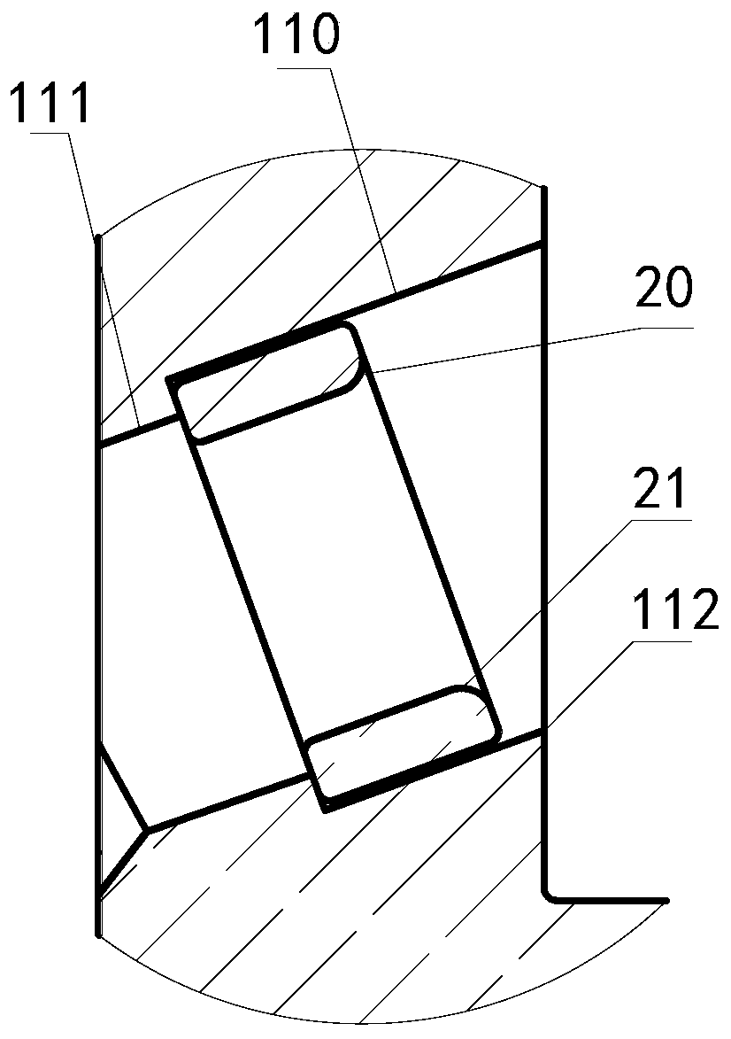
[0042] see picture figure 1 and figure 2 As shown, the embodiment of the present invention provides a layered type optical cable twist head outlet cover plate mold, which includes a body 1 and a plurality of low friction coefficient backing rings 2, and the body 1 is provided with reinforcement passing holes 10 and distributed in the The reinforcing member passes through a plurality of reaming holes 11 around the hole 10, and the distance between the inlet end of the reaming hole 11 and the reinforcing member passing hole 10 is greater than the distance between its outlet end and the reinforcing member passing hole 10 The low friction coefficient backing ring 2 is embedded in the reamed hole 11, and the reaming hole 11 and the low friction coefficient backing ring 2 located in the reaming hole 11 are arranged coaxially. see image 3 As shown, a chamfer 20 is provided on the inner wall of the low friction coefficient backing ring 2 near the inlet end of the reamed hole 11 . ...


PUM


Abstract

The invention discloses a layer-stranded cable winch outlet cover plate mould and a stranding platform. The layer-stranded cable winch outlet cover plate mould comprises a body. The body is provided with a reinforcing member through hole and a plurality of reaming holes distributed around the reinforcing member through hole. The distance between the reaming hole inlet end and the reinforcing member through hole is greater than the distance between the outlet end thereof and the reinforcing member through hole. According to the invention, by setting the reaming hole as an inclined hole, a sleeve is changed from the outlet end of the reaming hole into the inlet end thereof by a support point which changes direction; when the sleeve enters the reaming holes and moves forward along the axial direction of the reaming holes, the sleeve contacts the wall, which is close to the reinforcing member through hole, of the reaming holes; the contact area becomes larger; the interaction force betweenthe sleeve and a winch outlet cover plate is reduced, so that the wear period of the winch outlet cover plate is prolonged; the problem of tube difference caused by inconsistent resistance of the sleeve due to different degrees of wear of the winch outlet cover plate is avoided; and tension acting on the sleeve is stable and controllable.

Description

technical field [0001] The invention relates to the technical field of optical cable manufacturing equipment, in particular to a layer-twisted optical cable twist head exit cover mold and a twisting table. Background technique [0002] During the SZ stranding process of the layer-stranded optical cable, the sleeve needs to pass through the twisting table for stranding. When entering the paralleling mold, there is a clamp between the movement direction of the sleeve and the axial direction of the through hole on the stranding head for the strengthening member to pass through. Angle, while the reinforcing member passage hole on the cover plate of the twisting head outlet is coaxially arranged with the twisting head outlet. The process of casing from being parallel to the strengthening member to contacting and twisting with the strengthening member requires external force to change the progress of the casing. direction, and then carry out the stranding process. [0003] Howeve...

Claims


Application Information

Patent Timeline
Patent Type & Authority Patents(China)
IPC IPC(8): G02B6/44
CPCG02B6/4479G02B6/4486G02B6/449
Inventor 王子轩潘强斌沈斐
Owner FENGHUO COMM SCI & TECH CO LTD
Why Eureka
Try Eureka