
electrical connector

A technology for electrical connectors and connecting parts, which is applied in the direction of connection, two-part connection devices, and parts of connection devices, etc. It can solve the problems of affecting the functional characteristics of electrical connectors, the tongue plate is easy to hit the butt connector, and the terminals are short-circuited. , to achieve the effect of ensuring strength and fixing effect, avoiding short circuit of shielding sheet and avoiding contact short circuit

Active Publication Date: 2019-10-01
DEYI PRECISION ELECTRONIC IND CO LTD PANYU
View PDF4 Cites 1 Cited by
  • Summary
  • Abstract
  • Description
  • Claims
  • Application Information

AI Technical Summary

Problems solved by technology

When the electrical connector is docked with the butt connector, the tongue plate will enter into the butt connector. The heads are closely arranged, and the heads are just facing the shielding sheet, so the deformed head is easy to touch other adjacent heads or shielding sheets in the vertical direction, causing a short circuit between the terminals, or a short circuit between the terminal and the shielding sheet , thus affecting the functional characteristics of the entire electrical connector

Method used


Image

  • electrical connector
  • electrical connector
  • electrical connector

Examples


Embodiment Construction

[0039] In order to facilitate a better understanding of the purpose, structure, features, and effects of the present invention, the present invention will now be further described in conjunction with the accompanying drawings and specific embodiments.

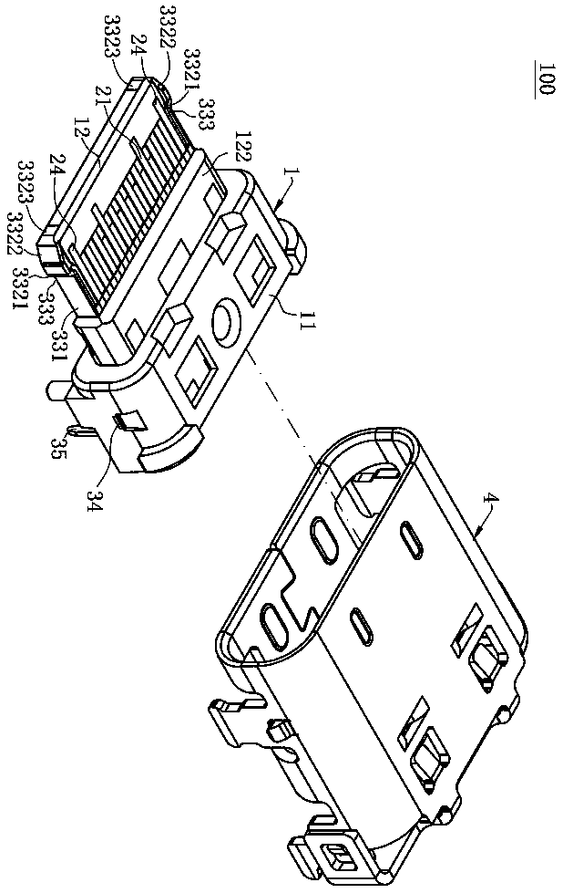
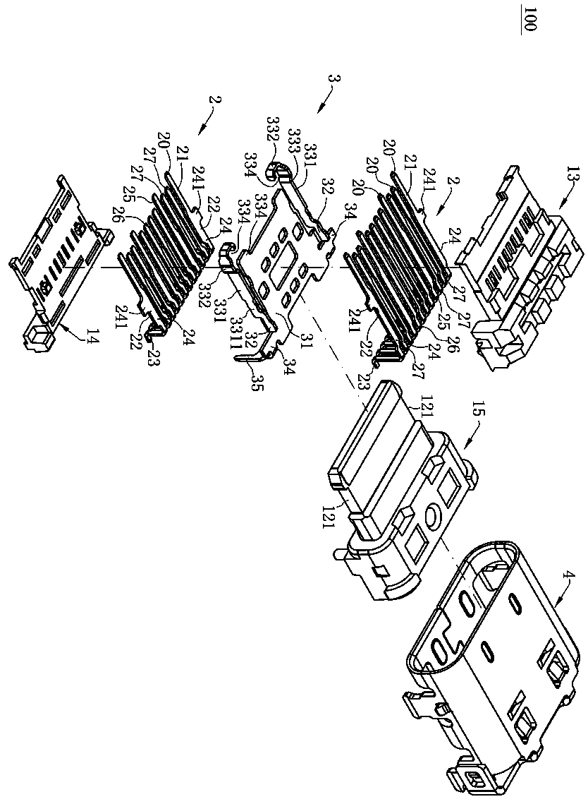
[0040] Such as figure 1 and figure 2 As shown, the electrical connector 100 of the present invention includes an insulating body 1 , two rows of terminals 2 accommodated in the insulating body 1 , a shielding piece 3 , and a shielding shell 4 covering the insulating body 1 .

[0041] Such as figure 1As shown, the insulating body 1 is provided with a base 11 , a tongue 12 extending forward from the base 11 , the tongue 12 is provided with a stepped portion 122 at the connection between the tongue 12 and the base 11 . A groove 121 is formed on the left and right side surfaces of the tongue plate 12 respectively.

[0042] Such as figure 1 and figure 2 As shown, each terminal 2 is provided with a contact portion 21, a weldin...


PUM


Abstract

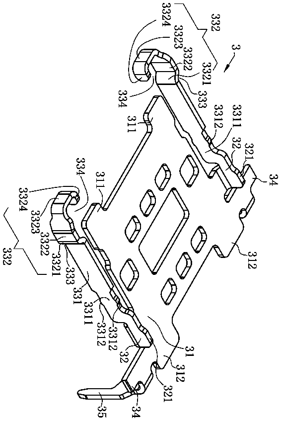
The invention discloses an electrical connector, which is characterized in that it comprises an insulating body, a base and a tongue plate extending forward from the base, at least one groove is provided on the side of the tongue plate; a shielding sheet is provided On the insulating body, the shielding sheet is provided with a plate body and at least one extension portion located on the side of the plate body, the plate body is disposed on the insulation body, the extension portion is disposed on the side of the tongue plate, and the extension portion includes a locking groove exposed in the groove. and a bent portion exposed on the tongue plate, the bent portion is located in front of the plate body, and is spaced from the plate body back and forth; a plurality of terminals are accommodated in the insulating body, and each terminal includes a head buried in the tongue plate, And in the front-to-back direction, each head is located between the bending part and the plate body. The bending part made of metal is wear-resistant and impact-resistant. The contact between the heads in the direction is short-circuited, avoiding the short-circuit caused by the contact of the heads with the shielding sheet, and ensuring high-frequency performance.

Description

technical field [0001] The invention relates to an electric connector, especially an electric connector with good strength and good high-frequency effect. Background technique [0002] An existing electrical connector includes an insulating body, two rows of terminals and a shielding piece, the shielding piece is located between the two rows of terminals and is fixed on the insulating body together, wherein the insulating body has a front extending The tongue plate, each terminal includes a head embedded in the tongue plate, and the upper row of heads is located directly above the shielding sheet, and the lower row of heads is located directly below the shielding sheet. When the electrical connector is docked with the butt connector, the tongue plate will enter into the butt connector. The heads are closely arranged, and the heads are just facing the shielding sheet, so the deformed head is easy to touch other adjacent heads or shielding sheets in the vertical direction, ca...

Claims


Application Information

Patent Timeline
Patent Type & Authority Patents(China)
IPC IPC(8): H01R13/02H01R13/502H01R13/6581H01R13/504
CPCH01R13/02H01R13/652H01R13/6581H01R13/6597H01R13/502H01R13/504H01R13/516H01R13/648H01R13/6591H01R13/6585H01R2107/00H01R24/60H01R13/6594H01R24/64H01R13/639
Inventor 冯武
Owner DEYI PRECISION ELECTRONIC IND CO LTD PANYU
Learn More