
electrical connector

A technology for electrical connectors and contact parts, which is applied in the direction of connection, fixed connection, and parts of connecting devices, etc., can solve the problem of unguaranteed signal transmission quality, crosstalk between ground terminals and signal terminals, and affecting the high frequency of electrical connectors. performance and other issues, to achieve the effect of reducing crosstalk and crosstalk, reducing interference, and increasing distance

Active Publication Date: 2020-06-09
DEYI PRECISION ELECTRONIC IND CO LTD PANYU
View PDF4 Cites 0 Cited by
  • Summary
  • Abstract
  • Description
  • Claims
  • Application Information

AI Technical Summary

Problems solved by technology

A known electrical connector for electrically connecting a mating element includes a body, a plurality of terminals are arranged in two rows in the body, the terminal has a base, and a contact portion extends from one end of the base to connect with the mating element. For electrical connection, a lead part is bent and extended from the other end of the base to expose the body. The lead parts of the same row of terminals are bent in the same direction, and the lead parts of different rows of terminals are bent in opposite directions. Multiple terminals include multiple signal terminals With multiple ground terminals, two adjacent signal terminals in the same row are located between two adjacent ground terminals. Although this design increases the shielding effect of the ground terminals, crosstalk and crosstalk are likely to occur between the ground terminals and the signal terminal pairs. , affect the high-frequency performance of the electrical connector, resulting in the quality of signal transmission cannot be guaranteed

Method used


Image

  • electrical connector
  • electrical connector
  • electrical connector

Examples


Embodiment Construction

[0036] In order to better understand the content of the present invention, the present invention will be further described in detail in conjunction with specific embodiments and illustrations.

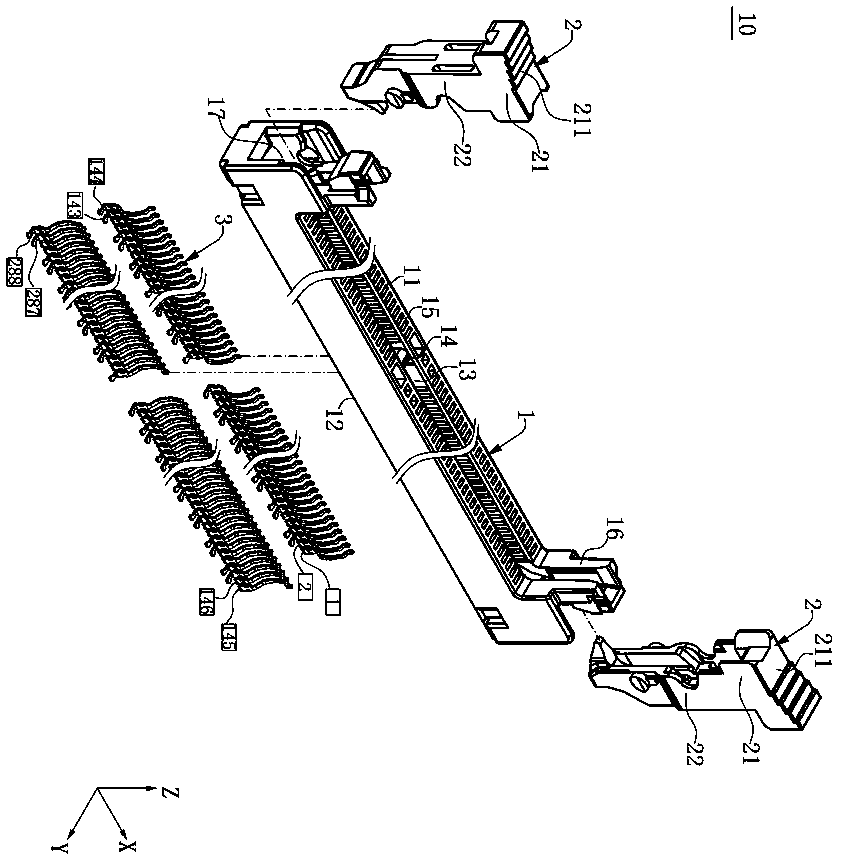
[0037] For the convenience of description, define the x-axis as the front-back direction, the y-axis as the left-right direction, and the z-axis as the up-down direction.

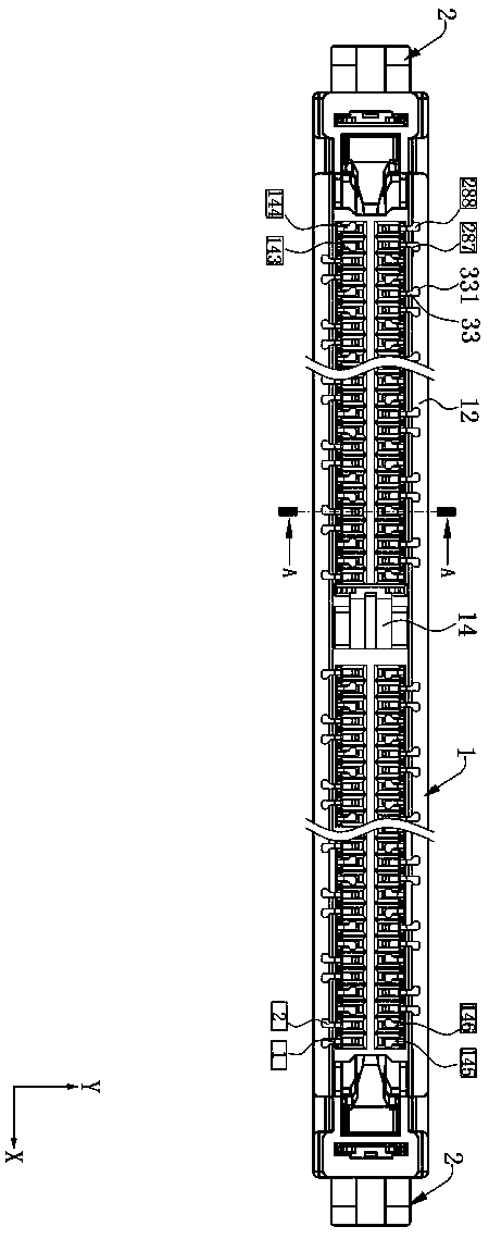
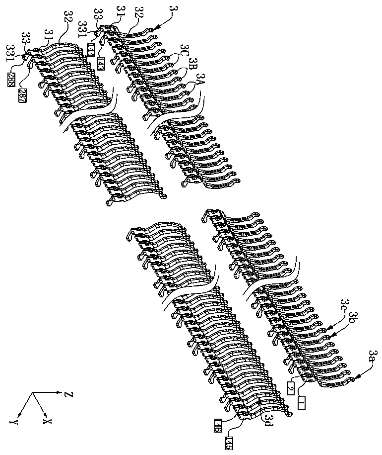
[0038] see figure 1 , is an electrical connector 10 of the present invention, which is used to connect a docking component (not labeled) and an electronic component (not labeled). In this embodiment, the docking component is an electronic card and is installed from top to bottom to In the electrical connector 10, the electronic component is a circuit board. The electrical connector 10 includes a main body 1 , two ear buckles 2 held on the main body 1 , and a plurality of terminals 3 arranged in two rows on the left and right along the X-axis direction on the main body 1 .

[0039] see figure 1 and figure 2 , th...


PUM


Abstract

An electrical connector includes multiple signal terminals and multiple ground terminals paired to form multiple terminal groups and arranged in one row in a body. One signal terminal and one ground terminal form a first terminal group. Two signal terminals form a second terminal group. One ground terminal and one signal terminal form a third terminal group. An arrangement order of the two terminals in the third terminal group is different from an arrangement order of the two terminals in the first terminal group. Each terminal has a conducting portion. The conducting portions of the terminals in a same terminal group bend in a same direction, and the conducting portions of the terminals in adjacent terminal groups bend in opposite directions. The second terminal group is located between the first terminal group and the third terminal group, and between the adjacent ground terminals.

Description

technical field [0001] The invention relates to an electrical connector, in particular to an electrical connector realizing high-frequency performance. Background technique [0002] Nowadays, electrical connectors have been used in various fields of life. With the development of science and technology, the exchange rate of information is getting faster and faster. Therefore, the requirements for electrical connectors are getting higher and higher. Not only are electrical connectors required to support The fast transmission rate also needs to improve the stability of signal transmission of the electrical connector. A known electrical connector for electrically connecting a mating component includes a body, a plurality of terminals are arranged in two rows in the body, the terminal has a base, and a contact portion extends from one end of the base to connect with the mating component. For electrical connection, a lead part is bent and extended from the other end of the base t...

Claims


Application Information

Patent Timeline
Patent Type & Authority Patents(China)
IPC IPC(8): H01R12/73H01R13/6471
CPCH01R12/73H01R13/6471H01R12/57H01R12/707H01R12/716H01R12/737H01R13/64H01R12/712H01R13/6477
Inventor 蔡友华
Owner DEYI PRECISION ELECTRONIC IND CO LTD PANYU
Learn More