A Directional Bridge Based on Coupling Capacitance

A bridge and capacitor technology, applied in the field of directional bridges based on coupling capacitors, can solve the problems of deterioration of output amplitude and phase balance characteristics, broadening of the low frequency lower limit, signal imbalance, etc., to improve low-frequency response capability and ensure high-frequency performance. , the effect of compensating for performance degradation

Inactive Publication Date: 2017-07-14
CHINA ELECTRONIS TECH INSTR CO LTD
View PDF5 Cites 0 Cited by
  • Summary
  • Abstract
  • Description
  • Claims
  • Application Information

AI Technical Summary

Problems solved by technology

[0004] It can be seen that the performance of the bridge is greatly affected by the fixed-ratio power-dividing characteristics of the power dividing circuit and the balance characteristics of the balun. Since the low-frequency characteristics of the balun are limited by the magnetic permeability of the magnetic core and its own volume, as the lower limit frequency decreases, the balance of the two circuits The balance characteristics of the output amplitude and phase deteriorate rapidly, and the two signals at the coupling end of the resistance power are unbalanced, and the isolation and directivity deteriorate seriously.
The simple balun broadband design and the existing resistive power divider circuit design scheme are difficult to broaden the low frequency lower limit while maintaining high frequency performance, so its frequency band adaptability is not particularly ideal
[0005] Therefore, it is difficult for existing bridges to take into account the needs of low-frequency applications of megahertz and below and high-frequency applications above 10GHz

Method used


Image

  • A Directional Bridge Based on Coupling Capacitance
  • A Directional Bridge Based on Coupling Capacitance
  • A Directional Bridge Based on Coupling Capacitance

Examples


Embodiment Construction

[0020] The following will clearly and completely describe the technical solutions in the embodiments of the present invention with reference to the accompanying drawings in the embodiments of the present invention. Obviously, the described embodiments are only some, not all, embodiments of the present invention. Based on the embodiments of the present invention, all other embodiments obtained by those skilled in the art without making creative efforts belong to the protection scope of the present invention.

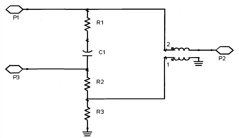
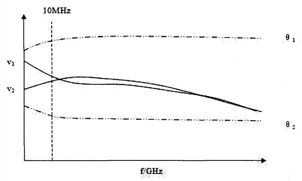
[0021] The present invention introduces the design of the coupling capacitor on the basis of the working characteristics of the current balun and resistance power dividing circuit, so that the working characteristics of the coupling capacitor and the original frequency response characteristics are mutually compensated in the low frequency band, so as to improve the electrical performance of the directional bridge , so that the amplitude-frequency response of the low-freque...


PUM


Abstract

The present invention proposes a directional bridge based on coupling capacitance, including: a power dividing circuit and a coaxial balun; the power dividing circuit includes a first resistor, a first capacitor, a second resistor and a third resistor connected in series ; The first port is connected to the third port through the first resistor and the first capacitor, and the third port is also connected to the ground potential through the second resistor and the third resistor; the coaxial balun includes a coaxial line and a magnetic ring, The magnetic ring is sleeved on the coaxial line, the coaxial line includes an outer conductor and an inner conductor, the first end of the outer conductor is connected to the common end of the second resistor and the third resistor, and the first end of the inner conductor is connected to the first Port, the first end of the outer conductor and the first end of the inner conductor together form a coaxial balanced end; the second end of the inner conductor is an unbalanced end, connected to the second port, and the second end of the outer conductor is grounded. The present invention makes the operating frequency lower under the premise of ensuring that the high-frequency characteristics are not affected.

Description

technical field [0001] The invention relates to the field of microwaves, in particular to a directional bridge based on coupling capacitance. Background technique [0002] Directional bridges are widely used in phase shifting, power synthesis and distribution, power sampling, directional coupling, directional detection, and dynamic monitoring of signal sources. They are key components in microwave systems and test and measurement. Microwave systems and microwave measuring instruments face the current demand for broadband use, and also have higher requirements for the ultra-wideband performance of the directional bridge. The most typical signal directional separation scheme in general applications is a directional coupler based on a tapered coupling line, which can achieve multi-octave high-directional signal directional separation, but the electrical length is longer at low frequencies, and the length of the coupling line is limited. It is difficult to achieve a relatively ...

Claims


Application Information

Patent Timeline
Patent Type & Authority Patents(China)
IPC IPC(8): G01R17/00
Inventor 葛新灵王飞李玉刚
Owner CHINA ELECTRONIS TECH INSTR CO LTD
Why Eureka
Try Eureka