Device and method for measuring z-axis vibration displacement

A vibration displacement, Z-axis technology, applied in the direction of measuring devices, instruments, etc., can solve the problems that the measurement method cannot accurately measure the Z-axis displacement of the vehicle, affect the application and promotion of active vibration reduction technology, and lead or lag the phase angle, etc. The effects of mass production and popularization, improved structure compactness and reliability, and good low-frequency response performance

Active Publication Date: 2018-01-12
上海新纪元机器人有限公司
View PDF3 Cites 0 Cited by
  • Summary
  • Abstract
  • Description
  • Claims
  • Application Information

AI Technical Summary

Problems solved by technology

[0003] However, the applicant found that the existing measurement method has a serious integral drift caused by signal noise, especially when the signal is low frequency or is stationary
Moreover, low-pass, high-pass or Calman filtering methods will introduce the problem of leading or lagging the phase angle, which cannot be integrated for a long time to accurately measure the displacement of the vehicle vibrating up and down in the Z-axis direction
[0004] In the application fields such as vehicle-mounted self-balancing and stable platforms, the existing measurement methods cannot accurately measure the Z-axis displacement of the vehicle bumping up and down during driving, which greatly affects the application and promotion of active vibration reduction technology.

Method used


Image

  • Device and method for measuring z-axis vibration displacement
  • Device and method for measuring z-axis vibration displacement
  • Device and method for measuring z-axis vibration displacement

Examples


Embodiment 1

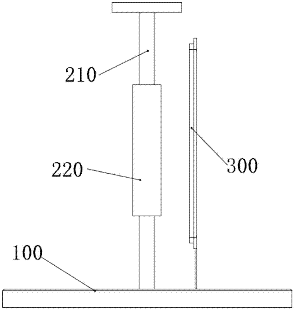
[0037] like figure 1 As shown, the present embodiment discloses a device for measuring Z-axis vibration displacement, which includes an installation base 100, a linear motor 200 and a displacement sensor 300. The stator 210 of the linear motor 200 is arranged on the installation base 100, and the displacement sensor 300 It is used to measure the relative displacement of the mover 220 and the stator 210 of the linear motor 200 .

[0038] In this embodiment, the direction perpendicular to the horizontal ground is the Z axis, such as figure 1 As shown, a linear motor 200 is arranged along the Z-axis, and the mover 220 of the linear motor 200 slides in the Z-axis direction.

[0039] When the linear motor 200 is activated, the magnitude of the magnetic field force on the mover 220 in the Z-axis direction is greater than or equal to the magnitude of the mover 220's own gravity in the Z-axis direction, and the direction is opposite, and the mover 220 maintains a suspension with a su...

Embodiment 2

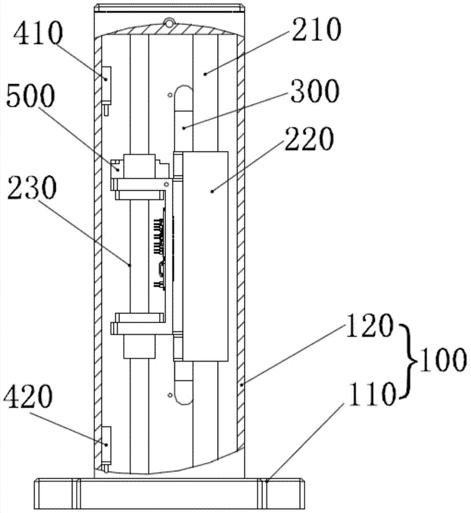
[0044] like figure 2 , image 3 and Figure 4 As shown, this embodiment discloses a device for measuring Z-axis vibration displacement, which includes a mounting base 100 , a linear motor 200 , a displacement sensor 300 , a limit switch 400 and a mass 500 .

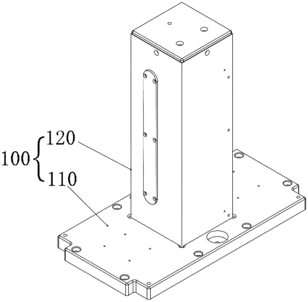
[0045] Specifically, as figure 2 and image 3As shown, the mounting base 100 of this embodiment includes a mounting base 110 and a housing shield 120 , the mounting base 110 is a rectangular flat plate, and the housing shield 120 is a hollow rectangular cover with one end open.

[0046] The stator 210 of the linear motor 200 of the present embodiment is vertically fixed on the installation base 110, and the housing shield 120 is covered on the installation base 110, forming a closed shielding space inside, and the linear motor 200 and the displacement sensor 300 are all located in the housing shield 120 internal.

[0047] Exemplarily, the displacement sensor 300 of this embodiment selects the grating scale, and the...

Embodiment 3

[0058] like Figure 1-8 As shown, this embodiment discloses a method for measuring Z-axis vibration displacement: a linear motor 200 and a displacement sensor 300 are arranged on the surface to be measured, the stator 210 of the linear motor 200 is perpendicular to the surface to be measured, and the linear motor 200 The mover 220 is slidably sleeved on the stator 210 . Start the linear motor 200 and the displacement sensor 300, the mover 220 is suspended on the stator 210 under the action of the magnetic field force and its own gravity to keep the absolute position basically unchanged, and the stator 210 and the mover of the linear motor 200 are monitored by the displacement sensor 300 220 relative displacement data, so as to obtain the vibration displacement data of the surface to be measured.

[0059] Specifically, in this embodiment, the linear motor 200 and the displacement sensor 300 can be pre-assembled on an installation base 100 to form a device for measuring Z-axis ...


PUM


Abstract

The invention discloses a device and method for measuring Z-axis vibration displacement. The device includes a mounting base, a linear motor and a displacement sensor. The stator of the linear motor is arranged on the mounting base. The suspension that keeps the absolute position basically unchanged under the action of its own gravity is set on the stator. In the case of vibration in the Z-axis direction, the Z-axis vibration displacement is realized by measuring the relative displacement between the mover and the stator. Measurement. The invention cleverly utilizes the relative displacement of the linear motor mover and stator to directly, quickly, effectively and accurately reflect the Z-axis vibration displacement, and provides a new idea and solution for Z-axis vibration displacement measurement for those skilled in the art , It overcomes the defects such as signal noise introducing integral drift, and has good low-frequency response performance. It can be applied to various scenarios of measuring Z-axis displacement, especially suitable for measuring the Z-axis displacement of up and down bumps during vehicle driving.

Description

technical field [0001] The invention relates to the technical field of displacement measurement, in particular to a device and method for measuring Z-axis vibration displacement. Background technique [0002] At present, the measurement of the vibration displacement in the Z-axis direction in the prior art is mainly based on the quadratic integration of the acceleration sensor: S=at 2 / 2 (S: displacement, a: acceleration, t: time), and then the absolute displacement S in the Z-axis direction is obtained. [0003] However, the applicant found that the existing measurement method has serious integral drift caused by signal noise, especially when the signal is low-frequency or stationary. Moreover, the low-pass, high-pass or Karl diffuse filtering methods will introduce the lead or lag of the phase angle, so it is impossible to integrate for a long time and accurately measure the displacement of the vehicle up and down in the Z-axis direction. [0004] However, in application...

Claims


Application Information

Patent Timeline
Patent Type & Authority Patents(China)
IPC IPC(8): G01B21/02
Inventor 仇高延张家奇廖靖陈养彬
Owner 上海新纪元机器人有限公司
Why Eureka
Try Eureka