Shooting method and shooting terminal of multi-camera, and readable storage medium
What is AI technical title?
AI technical title is built by Patsnap AI team. It summarizes the technical point description of the patent document.
A multi-camera and shooting method technology, applied in the multi-camera field, can solve problems such as increasing product costs
Inactive Publication Date: 2018-09-04
TRULY OPTO ELECTRONICS
View PDF5 Cites 4 Cited by
Summary
Abstract
Description
Claims
Application Information
AI Technical Summary
This helps you quickly interpret patents by identifying the three key elements:
Problems solved by technology
Method used
Benefits of technology
Problems solved by technology
The use of dual cameras is very common on mobile terminals, and in order to achieve more shooting functions, multi-camera technology will be the future trend, but multiple cameras will directly increase the cost of the product
Method used
Image
Click on the blue label to locate the original text in one second.
Reading with bidirectional positioning of images and text.
Examples
Embodiment 1
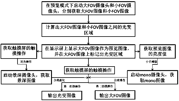
[0035] Such as figure 1 As shown, a multi-camera shooting method includes:
[0036] Get the shooting mode;
[0037] If the shooting mode obtained is IR mode, then start the RGB-IR switching camera and the IR emitter, and open the IR filter on the RGB-IR switching camera to obtain the IR image; if the shooting mode obtained is the optical variable mode, then Start the RGB-IR switching camera and the RGB camera, and turn off the IR filter on the RGB-IR switching camera to obtain small FOV images and large FOV images respectively;
[0038] Wherein, the viewing angle of the RGB-IR switching camera is smaller than that of the RGB camera.
[0039] The RGB-IR switching camera is a camera that uses an RGB photosensitive chip + a switchable IR filter. By opening and closing the IR filter, the IR filter enters and leaves the light channel of the camera. Among them, The IR filter can be located on the photosensitive surface of the RGB photosensitive chip, in the lens or in front of th...
Embodiment 2
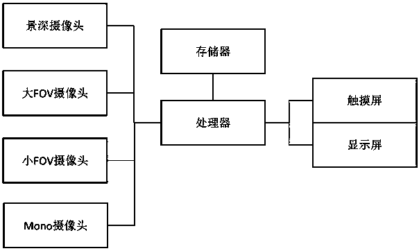
[0067] Such as figure 2 As shown, a multi-camera shooting terminal includes a processor, a memory electrically connected to the processor, a plurality of cameras and an IR emitter coplanarly arranged, and the memory stores information for the processor. Executing a computer program, when the processor executes the computer program, the multi-camera shooting method described in Embodiment 1 is performed.
[0068] Of course, the multi-camera shooting terminal also includes a display screen and a touch screen electrically connected to the processor, and the touch screen is arranged on the display surface of the display.
[0069] Preferably, the angle of view of the RGB camera is 100°-55°, and / or, the angle of view of the RGB-IR switching camera is 55°-30°; the optical center distance between the RGB camera and the RGB-IR switching camera 5-10mm. Preferably, the distance between the optical centers of the RGB camera and the mono camera is 5-10mm, and the field of view of the RG...
Embodiment 3
[0072] A readable storage medium stores a computer program for execution by a processor. When the processor executes the computer program, the multi-camera shooting method described in Embodiment 1 is performed.
PUM
Property
Measurement
Unit
Field of view
aaaaa
aaaaa
Abstract
The invention discloses a shooting method and shooting terminal of multi-camera, and a readable storage medium. The shooting method of the multi-camera comprises the following steps: acquiring a shooting mode; if the acquired shooting mode is an IR mode, starting a RGB-IR switching camera and an IR transmitter, and turning on an IR optical filter on the RGB-IR switching camera, thereby acquiring an IR image; starting the RGB-IR switching camera and a RGB camera if the acquired shooting mode is an optical variable mode, and turning off the IP optical filter on the RGB-IR switching camera, thereby respectively acquiring a small FOV image and a large FOV image, wherein the field of view angle of the RGB-IR switching camera is less than that of the RGB camera. Through the shooting method disclosed by the invention, the IR mode and the optical variable mode can be realized by adopting a RGB-IR switching camera with small field of view angle and the RGB camera with the large field of view angle.
Description
technical field [0001] The present invention relates to the field of multi-cameras, and in particular to a multi-camera shooting method, a shooting terminal and a readable storage medium. Background technique [0002] The rapid development of mobile terminals such as smart phones and tablet computers has made the functions of these mobile terminals more and more powerful, which has far exceeded the single function of communication. The shooting function is the most important function on the mobile terminal besides the communication. The use of dual cameras is very common in mobile terminals, and in order to achieve more shooting functions, multi-camera technology will be a future trend, but multiple cameras will directly increase the cost of the product. Contents of the invention [0003] In order to solve the above-mentioned shortcomings of the prior art, the present invention provides a multi-camera shooting method, a shooting terminal and a readable storage medium. Th...
Claims
Application Information
Patent Timeline
Application Date:The date an application was filed.
Publication Date:The date a patent or application was officially published.
First Publication Date:The earliest publication date of a patent with the same application number.
Issue Date:Publication date of the patent grant document.
PCT Entry Date:The Entry date of PCT National Phase.
Estimated Expiry Date:The statutory expiry date of a patent right according to the Patent Law, and it is the longest term of protection that the patent right can achieve without the termination of the patent right due to other reasons(Term extension factor has been taken into account ).
Invalid Date:Actual expiry date is based on effective date or publication date of legal transaction data of invalid patent.

