Long cavity laser sensor for large FOV auto-tracking

a laser sensor and long cavity technology, applied in the field of long cavity lasers, can solve the problems of generating noise, affecting the detection effect, and affecting the accuracy of object detection and auto-tracking,

Active Publication Date: 2014-12-30
LOCKHEED MARTIN CORP
View PDF62 Cites 2 Cited by
  • Summary
  • Abstract
  • Description
  • Claims
  • Application Information

AI Technical Summary

Problems solved by technology

Laser-based systems used in object detection and auto-tracking suffer from a number of difficulties and drawbacks.
This deficiency becomes more acute in an auto-tracking application where the detected objects may be moving across those same large areas.
This frequently is done using electromechanical means such as servo-motors, which give off noise, consume power, and generate heat.
Logistically, this complicates systems and drives them to larger sizes to accommodate these types of concerns.
It also reduces their stealth, thereby making them more vulnerable to countermeasures reducing or eliminating their effectiveness, sometimes to the point of destruction.

Method used


Image

  • Long cavity laser sensor for large FOV auto-tracking
  • Long cavity laser sensor for large FOV auto-tracking
  • Long cavity laser sensor for large FOV auto-tracking

Examples


Embodiment Construction

[0016]Illustrative embodiments of the invention are described below. In the interest of clarity, not all features of an actual implementation are described in this specification. It will of course be appreciated that in the development of any such actual embodiment, numerous implementation-specific decisions must be made to achieve the developers' specific goals, such as compliance with system-related and business-related constraints, which will vary from one implementation to another. Moreover, it will be appreciated that such a development effort, even if complex and time-consuming, would be a routine undertaking for those of ordinary skill in the art having the benefit of this disclosure.

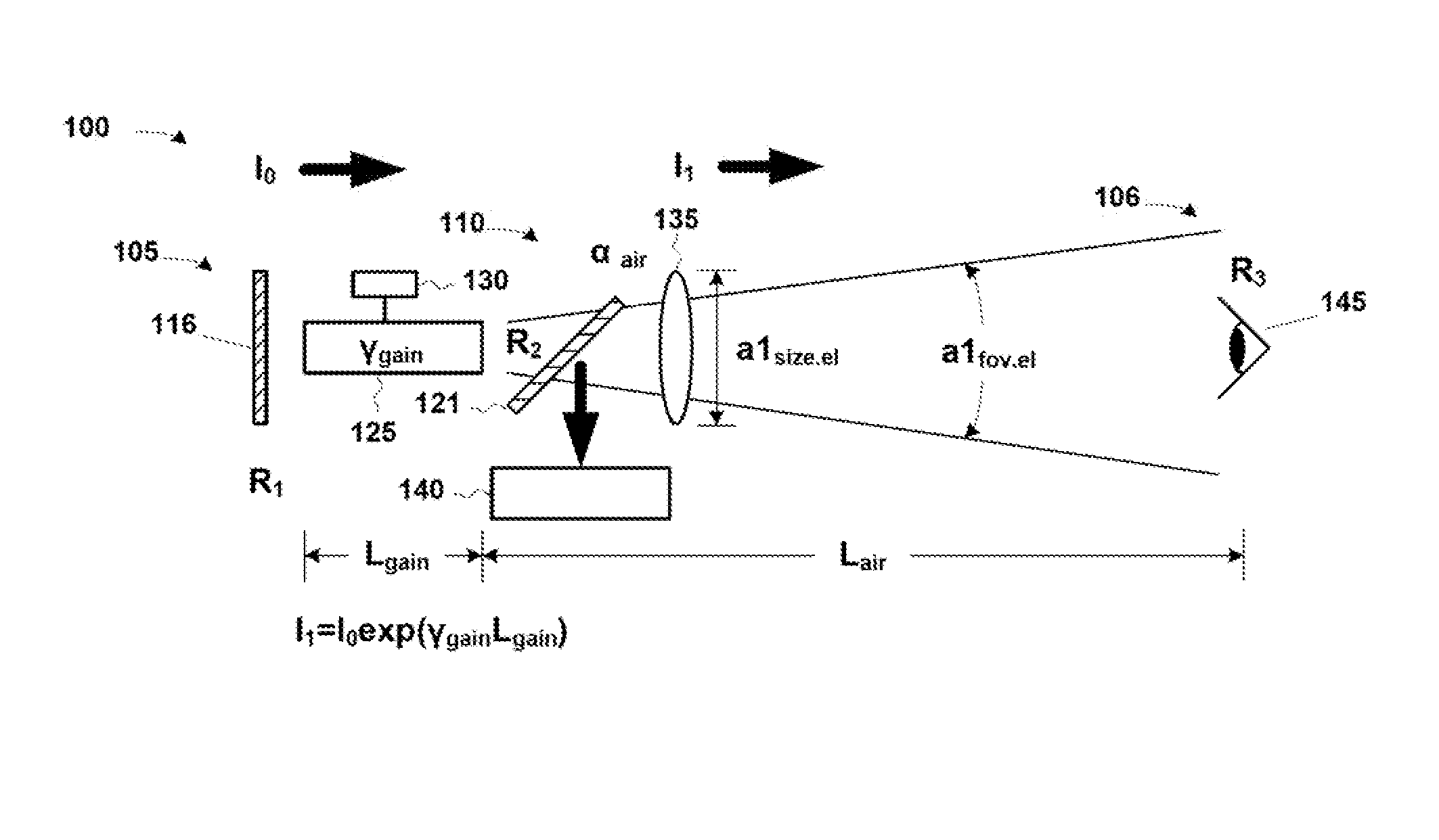
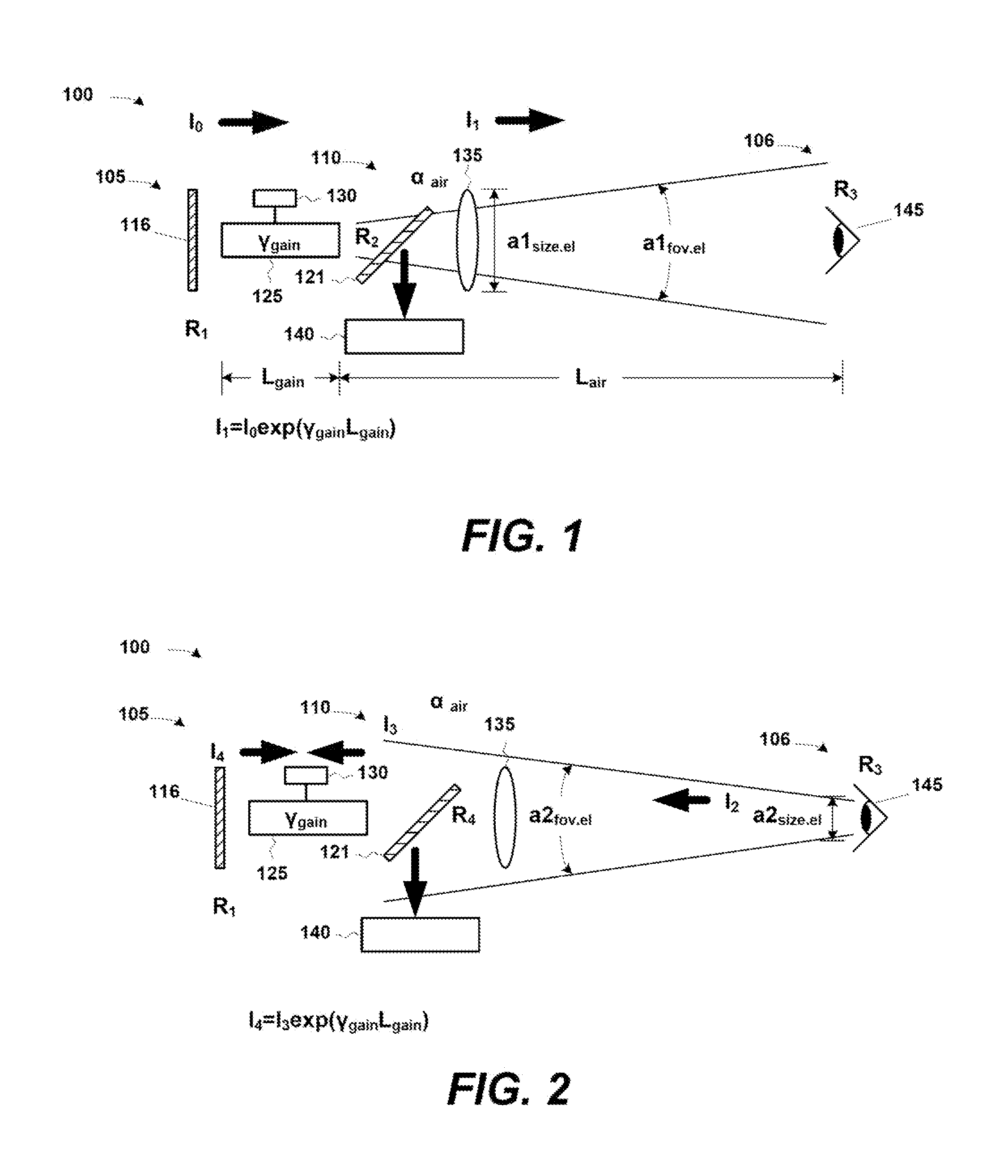
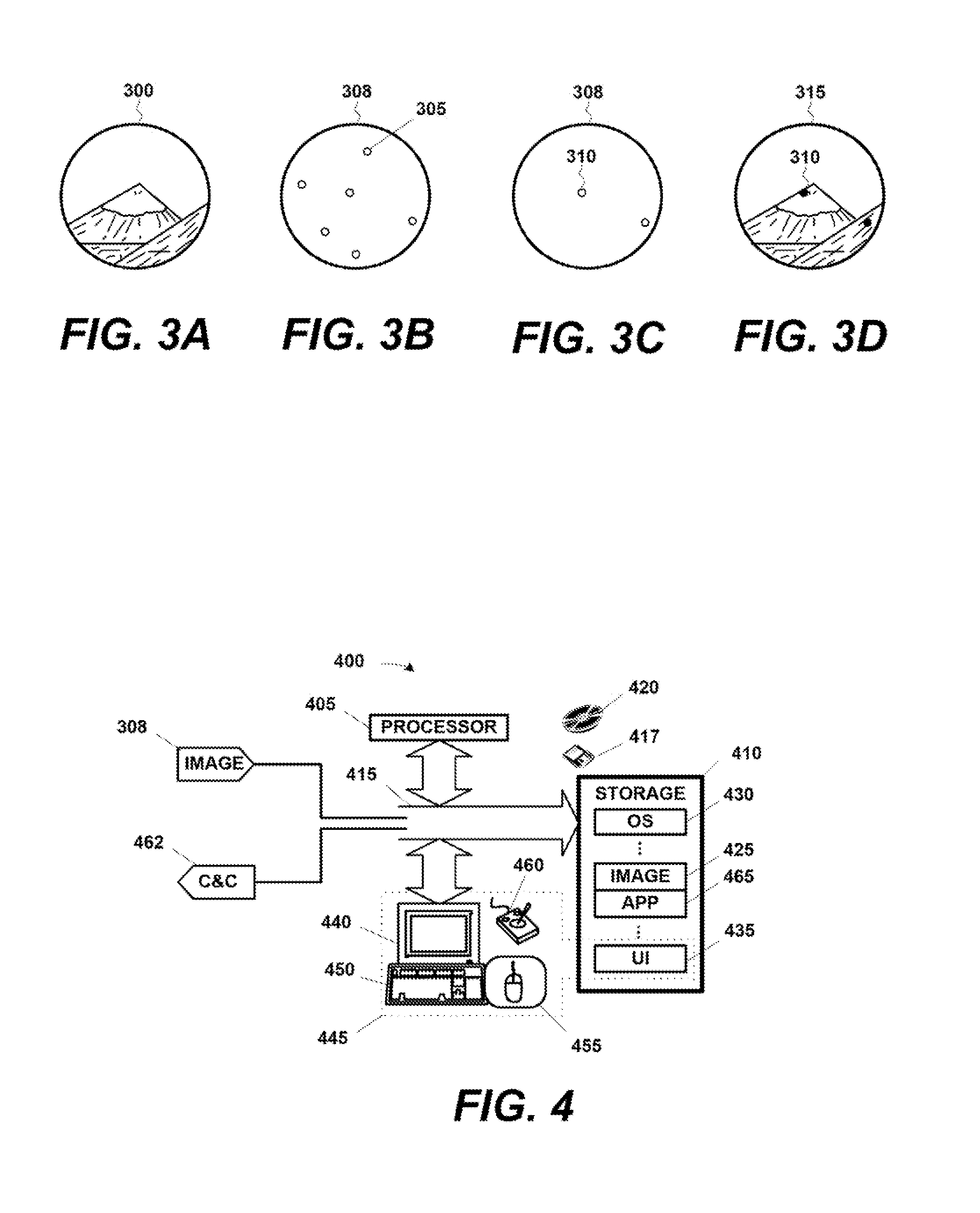
[0017]The presently disclosed laser-based technique provides auto-tracking within a large field of view (“FOV”) of personnel and materials using long cavity lasing. Electronic imaging sensors yield detailed information concerning the micromotions and time variation in reflectivity of targets. It ...


PUM


Abstract

The presently disclosed technique presents laser-based method and apparatus for use in remote sensing. In general, objects within a field of view are lased by a long cavity laser apparatus. Returns are detected, captured, and processed to identify actual objects of interest. These can then be communicated to a user. Over time, the actual objects of interest can be auto-tracked.

Description

CROSS-REFERENCE TO RELATED APPLICATIONS[0001]The priority to U.S. Provisional Application Ser. No. 61 / 371,404, filed on Aug. 6, 2010, entitled “Long Laser Sensor,” in the name of the inventors Paul Perryman et al., is hereby claimed pursuant to 35 U.S.C. §119(e). This provisional application is also hereby incorporated by reference for all purposes as if set forth verbatim herein.STATEMENT REGARDING FEDERALLY SPONSORED RESEARCH OR DEVELOPMENT[0002]Not applicable.BACKGROUND OF THE INVENTION[0003]The present invention pertains to detection and auto-tracking of objects in a field of view using a laser-based method and apparatus, and, more particularly, doing so with a long cavity laser.[0004]The following discussion introduces various aspects of the art that may be related to various aspects of what is described and / or claimed below. It provides background information to facilitate a better understanding of the various aspects of that disclosure. As the section's title implies, this is...

Claims


Application Information

Patent Timeline
Patent Type & Authority Patents(United States)
IPC IPC(8): H01S3/13G01S7/481G01S7/491G01S7/51G01S7/48H01S3/139G01S17/58G01S17/42
CPCG01C3/08G01S7/4808G01S7/4812H01S3/139G01S7/51G01S17/58H01S3/1306G01S7/4918G01S17/42G01S7/481G01S7/4916G01S17/66H01S3/0014H01S3/08H01S3/105H01S3/115
Inventor PERRYMAN, GARY PAULBROWDER, MARK K.WOOD, JAMES RICHARD
Owner LOCKHEED MARTIN CORP
Why Eureka
Try Eureka