Method for conducting a vibration diagnostic monitoring of a machine

A technology of machines and machine parts, which is applied in the field of devices implementing the method, can solve problems such as the difficulty in estimating the source of vibration behavior, the correlation of operating parameters of machine vibration behavior that cannot be measured in discontinuous motion, and the complexity of motion patterns, etc., to save calculations Effects of Time and Computing Power

Inactive Publication Date: 2018-09-04
FISCHER BRODBECK GMBH
View PDF5 Cites 9 Cited by
  • Summary
  • Abstract
  • Description
  • Claims
  • Application Information

AI Technical Summary

Benefits of technology

The technology described in this patented describes an automated way to determine if there are any abnormalities or variations in machinery's performance caused due to their periodic movements during operation. This helps identify causes like excessive wear or damage from overload conditions before they become more severe than usual.

Problems solved by technology

This patents discuss how faulty machining operations may lead to reduced productivity due to poor quality control caused by unstable rotation rates during certain stages of milling processes. These issues include decreased lifespan of machine tools (rotors) and bearing damage. Current techniques involve measuring static and dynamic properties like frequency and force levels, identifying potential causes of defects, predicting their progress towards further deteriorated conditions, and developing models based upon them. However, existing methods require significant human labor input and result in imprecise estimates of machine status and component characteristics.

Method used


Image

  • Method for conducting a vibration diagnostic monitoring of a machine
  • Method for conducting a vibration diagnostic monitoring of a machine
  • Method for conducting a vibration diagnostic monitoring of a machine

Examples


Embodiment Construction

[0082] The following will refer to Figure 1 to Figure 11 The invention is explained in detail, wherein the same reference numerals refer to the same structural and / or functional features.

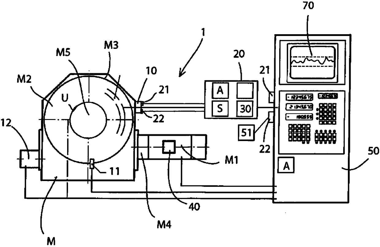
[0083] figure 1 A schematic diagram of a machine M (here a rotary table) is shown with machine components M1 , . . . , M5 and a device 1 with a vibration sensor 20 for measuring vibrations.

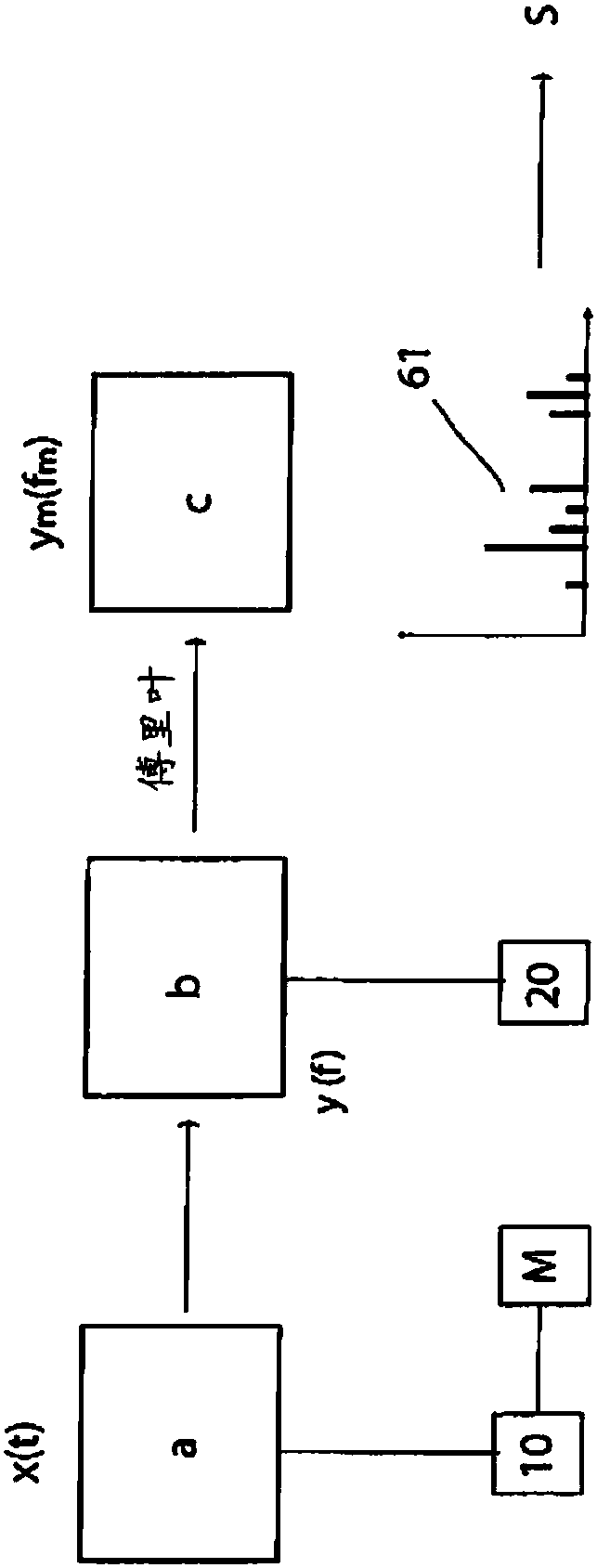
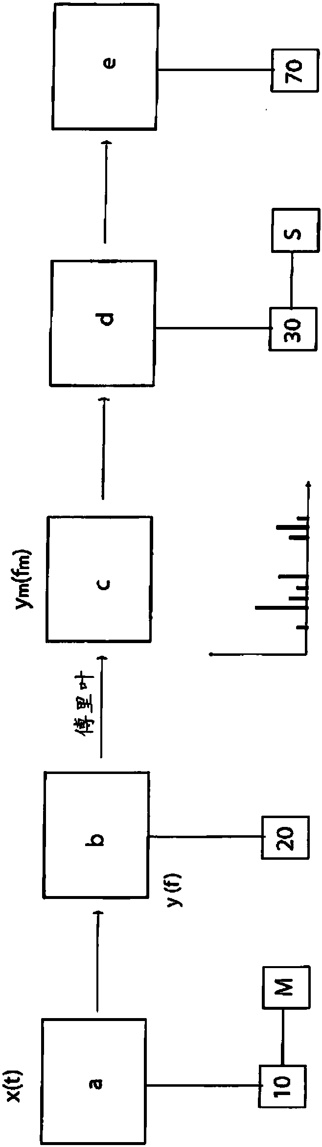
[0084] Device 1 is constructed to implement figure 2 and image 3 A method for vibration diagnostic monitoring and evaluation of individual machine parts M1, . . . , M5 of a machine M shown in the block diagram.

[0085] The machine M is equipped with a vibration sensor 10, which is used for discontinuous or continuous measurement and / or detection such as Figure 4 The time signal x(t) shown exemplarily in . Furthermore, other sensors not shown in detail in the figures (for example temperature sensors etc.) can be provided.

[0086] In this embodiment, the vibration sensor 10 detects the vibrat...


PUM


Abstract

The invention relates to a method and a device for carrying out a method for conducting a vibration diagnostic monitoring and assessment of individual machine parts (M1,... Mn) of a machine (M), preferably a rotary machine, using a frequency analyzer.

Description


Claims


Application Information

Patent Timeline
Owner FISCHER BRODBECK GMBH
Why Eureka
Try Eureka