
Machine tool comprising a device for collision monitoring

A technology of collision detection and machine tools, applied in metal processing equipment, measuring/indicating equipment, metal processing machinery parts, etc., can solve problems such as modification

Active Publication Date: 2012-08-01
DECKEL MAHO PFRONTEN GMBH
View PDF6 Cites 34 Cited by
  • Summary
  • Abstract
  • Description
  • Claims
  • Application Information

AI Technical Summary

Problems solved by technology

[0004] In such monitoring collision devices, the prior art collision limit value is predetermined by the manufacturer, for example, to a value of 20g (g represents the acceleration of gravity), which cannot be programmed by the machine operator or the control data of the CNC machine tool personnel modification

Method used


Image

  • Machine tool comprising a device for collision monitoring
  • Machine tool comprising a device for collision monitoring
  • Machine tool comprising a device for collision monitoring

Examples


Embodiment Construction

[0074] Preferred embodiments of the present invention are described in detail below with reference to the accompanying drawings. However, the invention is not limited to the described embodiments. The present invention is defined by the scope of the claims. Identical and / or similar features of the embodiments are denoted by the same numerical references.

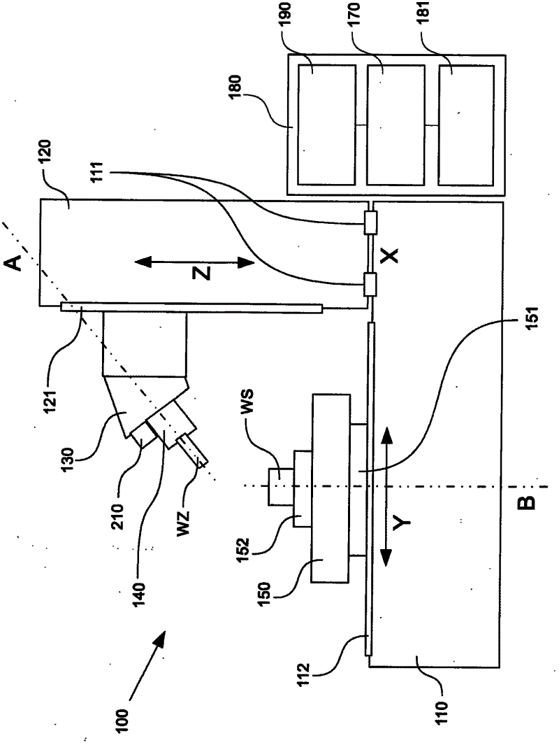
[0075] figure 1 A schematic diagram of an embodiment of a numerically controlled machine tool 100 for machining a workpiece WS is shown. The workpiece WS is clamped on a clamping device 152 provided on the turntable 150 of the machine tool 100, so that the workpiece is fixed in rotation and can be rotated by a rotating shaft B (see figure 1 The vertical rotation axis in the) rotation drive. As an embodiment, the turntable 150 can be moved by a support frame 151 installed on the Y-direction guide rail 112 on the bed 110 of the machine tool, and the support frame 151 moves along the Y guide rail 112 in the Y direction thro...


PUM


Abstract

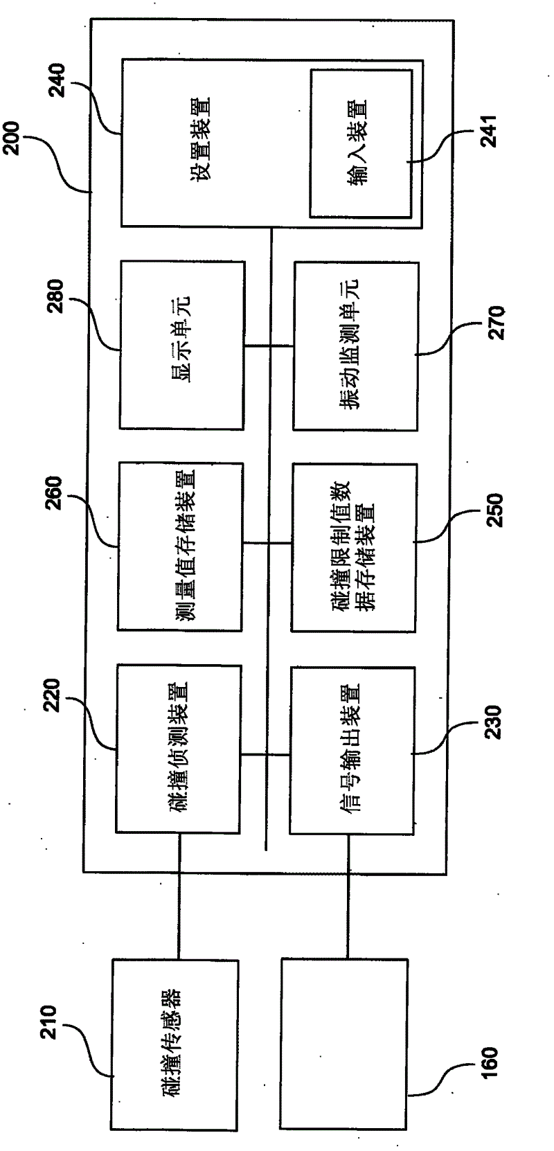
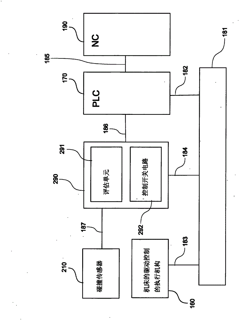
A numerically controlled machine tool for machining a workpiece is provided. The machine tool includes a work spindle(140), at least one feed axis(X,111;Y112;Z,121), and a device for collision monitoring(200) on said machine tool(100), wherein the device for collision monitoring(200) includes a collision sensor(210) mounted on a machine part of the machine tool, collision detection means(220,290) for detecting a collision of machine parts(130,140,152,150) of the machine tool(100) when a measuring value detected by the collision sensor exceeds a collision limit value, and signal output means for outputting a stop signal for stopping the at least one work spindle and the at least one feed axis(X,111;Y112;Z,121), of the machine tool when the collision detection means detects a collision. The machine tool (100)includes a unit for determining the collision limit value on the machine tool(100).

Description

technical field [0001] The invention relates to a numerically controlled machine tool for machining workpieces, having a working spindle, at least one feed axis and a collision monitoring device. The collision monitoring device includes a collision sensor installed on the machine tool processing part, a collision detection device for detecting the collision of the machine tool processing part when the measured value detected by the collision sensor exceeds the collision limit value, and when the collision detection device detects A signal output device for outputting a stop signal for stopping the at least one working spindle and the at least one feed axis of the machine tool in the event of a collision. Background technique [0002] In the prior art, a general device for monitoring collisions on a numerically controlled machine tool for machining workpieces is known, which consists of detecting a collision when a measurement value detected by a collision sensor of the colli...

Claims


Application Information

Patent Timeline
Patent Type & Authority Applications(China)
IPC IPC(8): B23Q17/00B23Q17/12
CPCG05B2219/37237G05B2219/37432G05B2219/49143G05B2219/49141G05B19/4061G05B2219/39082B23Q17/2208B23Q17/12
Inventor 罗夫·克特默
Owner DECKEL MAHO PFRONTEN GMBH
Learn More