Thermoplastic pultrusion die system and method

Active Publication Date: 2014-06-10
EBERT COMPOSITES
View PDF57 Cites 71 Cited by
  • Summary
  • Abstract
  • Description
  • Claims
  • Application Information

AI Technical Summary

Benefits of technology

[0021]In a further aspect of the invention, this capability is taken one step further. The thermoplastic pultrusion die system and method allows for temporary halting of the pultrusion direction as the grippers are another set of accurate axes of motion control. This halting can coincide with a very high compression force, actuated by the computer software. The purpose of this halting of gripper motion (and speed) and of the very high compressive force is to use the die cavity gap as a temporary compression molding die. This very high pressure may be one that exceeds the frictional capability of the pultrusion process. Then, after a defined period of time, the die cavity gap can be actuated and commanded to a larger gap position while the grippers start up again. As this part of the cycle occurs, easy release of the material in the die occurs. The composite is pulled with low friction and new material is allowed to enter the die cavity gap at low friction. As a result, the material, especially in thin parts, does not allow for sloughing of material (e.g., 90 degree tape). Therefore, an easy and defined entry into the die cavity is attained. The process is continued (the grippers stop pultruding, die cavity gap is closed to a very high pressure, and so on). This process described above can be so rapid that to an ordinary observer the process may look like the pultrusion rate of processing is at a steady speed when, in fact, that is not the case.
[0022]Furthermore, in addition to the above, a belt of finite length or an endless strap or band made of, for example, Teflon, steel, coated steel, high temperature PEEK, or any suitable band material, as described in Lambing, et al., U.S. Pa

Problems solved by technology

Although the panel referenced above was successfully pultruded, other types of composite material cross sections present different challenges.
These core materials present their own unique set of challenges.
For example, many times these core materials have high compressi

Method used


Image

  • Thermoplastic pultrusion die system and method
  • Thermoplastic pultrusion die system and method
  • Thermoplastic pultrusion die system and method

Examples


Embodiment Construction

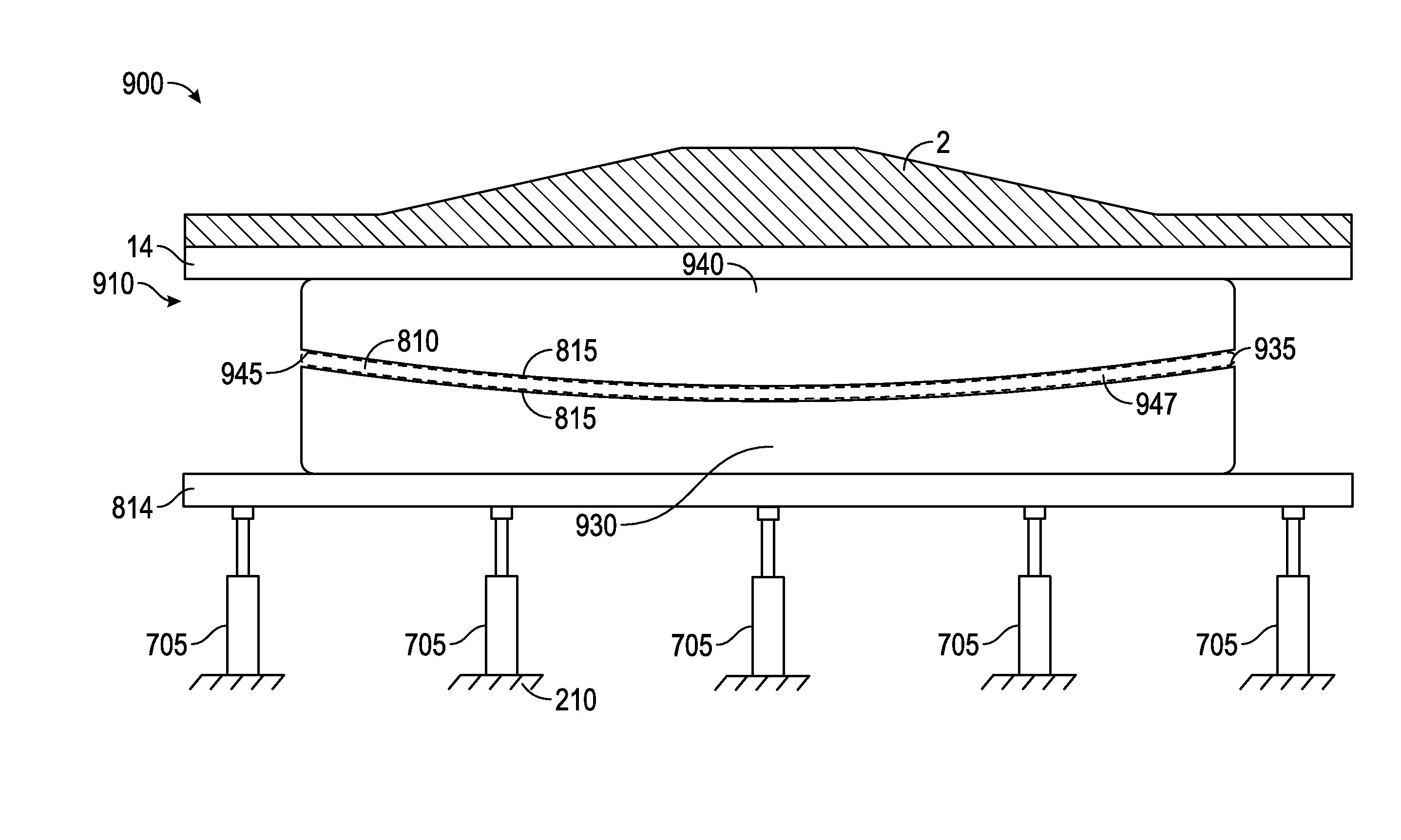
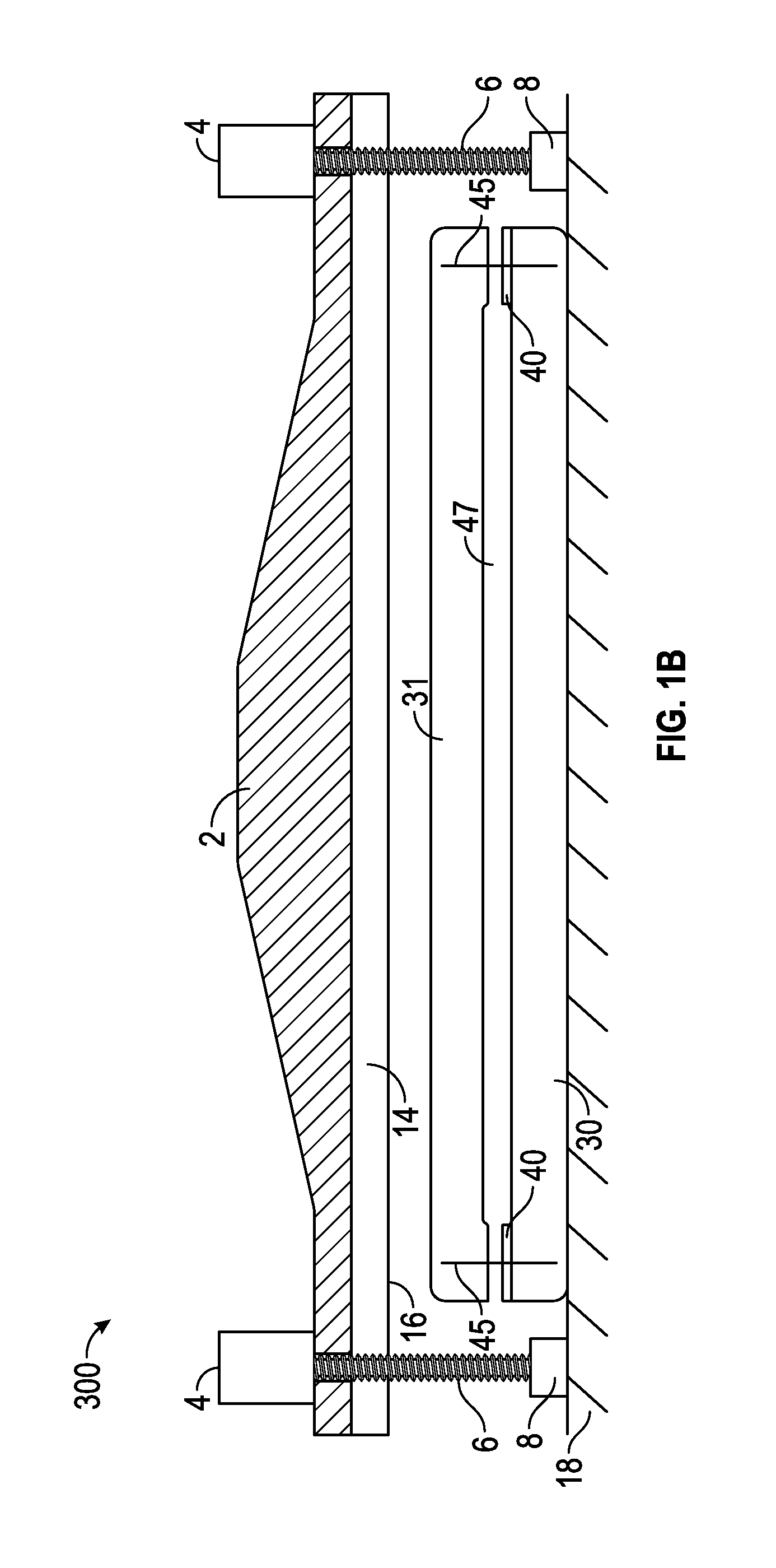
[0041]With reference to FIG. 1-8, an embodiment of a thermoplastic pultrusion die system (“system”) 300 and method of processing using the same will be described.

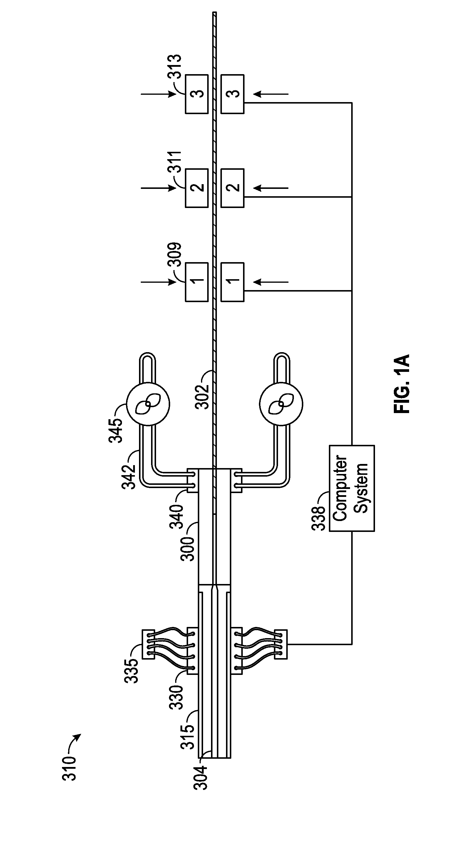
[0042]With reference to FIG. 1A, before describing the system 300, an embodiment of an exemplary thermoplastic composite tape pultrusion processing assembly 310 and method that the thermoplastic pultrusion die system 300 and method may be a part of will first be described.

[0043]In the thermoplastic composite tape pultrusion processing assembly 310, the pultrusion process moves from left to right. From left-to-right, the assembly 310 includes a tunnel oven 315, the thermoplastic pultrusion die system 300, and a pultrusion gripper mechanism including one or more grippers (e.g., one, two, three) 309, 311, 313 in series. In FIG. 1A, a fairly short thermoplastic pultrusion die system 300 is shown, but in actuality the thermoplastic pultrusion die system 300 may extend forward in the process 20 feet or more to assist with heating...


PUM

PropertyMeasurementUnit
Thicknessaaaaaaaaaa
Pressureaaaaaaaaaa
Speedaaaaaaaaaa

Abstract

A thermoplastic pultrusion die system for pultruding a thermoplastic composite includes a first pultrusion die member with a curved, concave top surface; a second pultrusion die member with a curved, convex bottom surface; a curved die cavity gap formed between the a curved, concave top surface of the first pultrusion die member and the curved, convex bottom surface of the second pultrusion die member; a die cavity gap adjustment mechanism that imparts movement to at least one of the first pultrusion die member and the second pultrusion die member to vary the die cavity gap from closed to a specified location to open at a specified location; a pultrusion gripper mechanism having one or more grippers in series, and a computer numerical control (CNC) computer system controlling the die cavity gap adjustment mechanism.

Description

CROSS REFERENCE TO RELATED APPLICATIONS[0001]This application is a continuation-in-part application of U.S. nonprovisional patent application Ser. No. 13 / 738,126, which was filed on Jan. 10, 2013, which issued as U.S. Pat. No. 8,684,722 on Apr. 1, 2014 which is a continuation of U.S. patent application Ser. No. 13 / 407,629 filed Feb. 28, 2012, which issued as U.S. Pat. No. 8,353,694 on Jan. 15, 2013, which is a continuation of Ser. No. 12 / 409,389 filed Mar. 23, 2009, which issued as U.S. Pat. No. 8,123,510 on Feb. 28, 2012 and claims priority to U.S. provisional patent application 61 / 070,754 filed Mar. 24, 2008 under 35 U.S.C. 119. The present application also claims priority to U.S. Provisional Patent Application 61 / 714,954 filed Oct. 17, 2012 under 35 U.S.C. 119. The above applications are incorporated by reference herein.FIELD OF THE INVENTION[0002]The present invention relates to composite material pultrusion systems and methods.BACKGROUND OF THE INVENTION[0003]In the past, a lay...

Claims


Application Information

Patent Timeline
IPC IPC(8): B29C47/16B29C47/92B29C48/31B29C48/92
CPCB29C70/526B29C47/92B29K2101/12
Inventor JOHNSON, DAVID W.GARRETT, SCOTT A.MOYERS, STEPHEN G.
Owner EBERT COMPOSITES
Why Eureka
Try Eureka