Ruled surface impeller tool path planning and processing method

A processing method and tool path technology, applied in the direction of instruments, computer control, simulators, etc., can solve the problem of not proposing the machining process of the integral ruled surface impeller, not giving the calculation method of the tool center point or the tool tip point, and unable to solve the problem. Realize problems such as five-axis machining of ruled surface impellers, and achieve the effect of overcoming low cutting efficiency, uniform distribution of tool paths, and orderly arrangement of flow channels

Inactive Publication Date: 2008-09-24
哈尔滨工大宏图橡塑科技有限公司
View PDF0 Cites 70 Cited by
  • Summary
  • Abstract
  • Description
  • Claims
  • Application Information

AI Technical Summary

Problems solved by technology

[0003] In order to solve the existing numerical control machining methods of impeller parts, the present invention does not propose a complete machining process for machining integral ruled surface impellers, does not provide calculation methods for knife center points or k

Method used


Image

  • Ruled surface impeller tool path planning and processing method
  • Ruled surface impeller tool path planning and processing method
  • Ruled surface impeller tool path planning and processing method

Examples


specific Embodiment approach 1

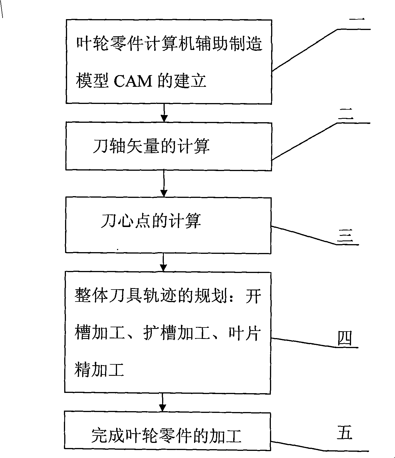
[0014] Specific implementation mode one: as figure 1 As shown, the tool trajectory planning and processing method of the ruled surface impeller described in this embodiment is realized according to the following steps:

[0015] Step 1. Establishment of the computer-aided manufacturing model CAM of the impeller parts: read the ordered value points (trajectory data) on the curve of the three-dimensional design drawing of the impeller by the CAM software, and use the approximation algorithm to process the read ordered value points Approximate fitting of various curves on the impeller to obtain the CAM model of the impeller parts;

[0016] In engineering, the shape of the impeller is generally designed according to the aerodynamic or fluid dynamic performance index, or measured by a three-coordinate measuring instrument. Either way, the data points generally given on the drawing describe the surface of the impeller blade. For an impeller with a ruled surface, the data points usu...

specific Embodiment approach 2

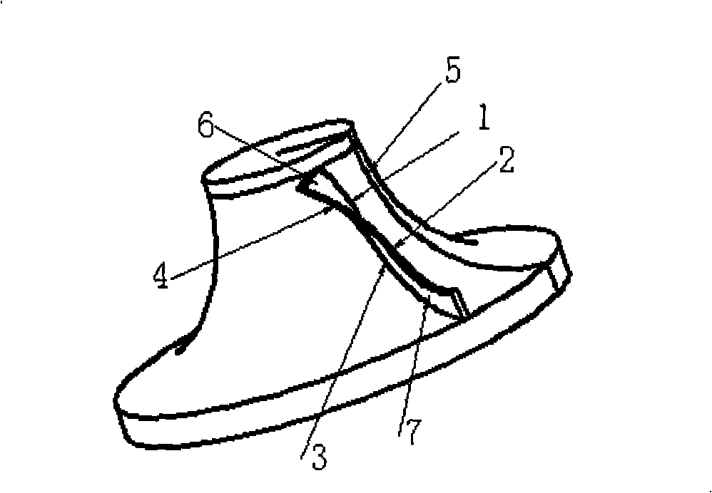
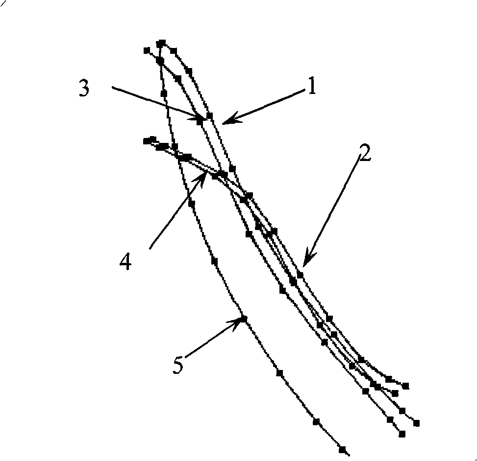
[0041] Specific implementation mode two: as figure 2 and image 3 As shown, the approximation algorithm in step 1 of this embodiment is to use the least squares method to perform the upper curve of the ruled surface impeller (blade back shaft disk curve 1, blade back cover disk curve 2, blade pot shaft disk curve 3, blade For the approximation of the pot cover curve 4 and the hub section line 5), the specific steps are as follows:

[0042] Step a, the ordered value point sequence P on the curve of the three-dimensional design diagram of the impeller to be read i (i=0,...,m) is constructed as a B-spline curve:

[0043] r ( u ) = Σ i = 0 n V i · N i , k ( u ...

specific Embodiment approach 3

[0053] Specific embodiment three: as shown in Figure 4 and Figure 6, the specific steps of the position calculation of the knife center point described in step 3 of the present embodiment are as follows:

[0054] Step i, first discretize the offset curved surface 9 of the impeller hub surface 8 into triangular pieces, and calculate the position of the intersection point by applying the triangle piece and the space directed line segment to find the intersection point, and the position of the intersection point is the position of the knife center point;

[0055] The discretization of the offset curved surface of the impeller hub surface into triangular pieces is carried out as follows:

[0056] One), according to the equal parameter method, calculate the derivative vector n3 of each point on the hub section line;

[0057] 2) The cross product of the guide vector and the unit normal vector of the plane where the hub section line is located obtains the normal vector n4 of the sect...


PUM

PropertyMeasurementUnit
Diameteraaaaaaaaaa
Diameteraaaaaaaaaa

Abstract

A path planning processing method of a ruled surface impeller cutter relates to a cutter path planning processing method. The invention solves the problems of the prior numerical control processing method of an impeller part, the problem are that a whole processing technology for processing a integral type ruled surface impeller is not proposed, the calculating method of the point of a knife centre or the point of a knifepoint is not given, the processing cutting efficiency is low, the operation is complex and the degree of automation is low and the five-axis processing of the ruled surface impeller can not be realized etc. The main steps of the method are the establishment of the calculator assistant manufacturing model CAM of an impeller part, the calculation of the vector of a cutter shaft, the calculation of the point of the knife centre, the planning of whole cutter path and the achievement of the processing of the impeller part. The method of the invention solves the problem of the five-axis processing of the ruled surface impeller and has the advantages of high processing cutting efficiency, easy operation and high degree of automation The ruled surface impeller processed by the method has the characteristics of orderly linage of flow passage, symmetrical structure and the uniform distribution of cutter path at the surface of the flow passage, thus reducing the workload of subsequent polishing processing greatly.

Description

technical field [0001] The invention relates to a tool track planning and processing method, in particular to a tool track planning and processing method for computer-aided manufacturing of an integral ruled surface impeller. Background technique [0002] CNC machining of impeller parts is a difficult technical problem in the field of mechanical processing. In the past, the machining method of impeller blades was usually adopted point milling. This method utilizes the tip of the milling cutter to cut the blade. Due to the small contact area between the cutting tool and the workpiece in this cutting method, the cutting amount is relatively small, which directly causes the impeller cutting processing time to be prolonged and reduces the processing efficiency. The shape of the impeller parts is complex, and it is difficult to complete the machining with the traditional three-axis machining center. During the machining process, the cutter shaft and the blades of the impeller w...

Claims


Application Information

Patent Timeline
IPC IPC(8): G05B19/4099
Inventor 富宏亚王永章韩振宇路华梁全刘源王显峰
Owner 哈尔滨工大宏图橡塑科技有限公司
Why Eureka
Try Eureka