Unmanned aerial vehicle (100) return path planning method and device

A return-to-home path and UAV technology, applied in the field of UAVs, can solve the problems of return-to-home failure and stuck in

Pending Publication Date: 2018-09-04
SZ DJI TECH CO LTD
View PDF22 Cites 30 Cited by
  • Summary
  • Abstract
  • Description
  • Claims
  • Application Information

AI Technical Summary

Problems solved by technology

The above drone return strategy does not consider the impact of the restricted flight zone. During the return process, the drone may be hindered by the restricted flight zone, resulting in the failure of the return flight and being stuck on the edge of the restricted flight zone.

Method used


Image

  • Unmanned aerial vehicle (100) return path planning method and device
  • Unmanned aerial vehicle (100) return path planning method and device
  • Unmanned aerial vehicle (100) return path planning method and device

Examples


Embodiment 1

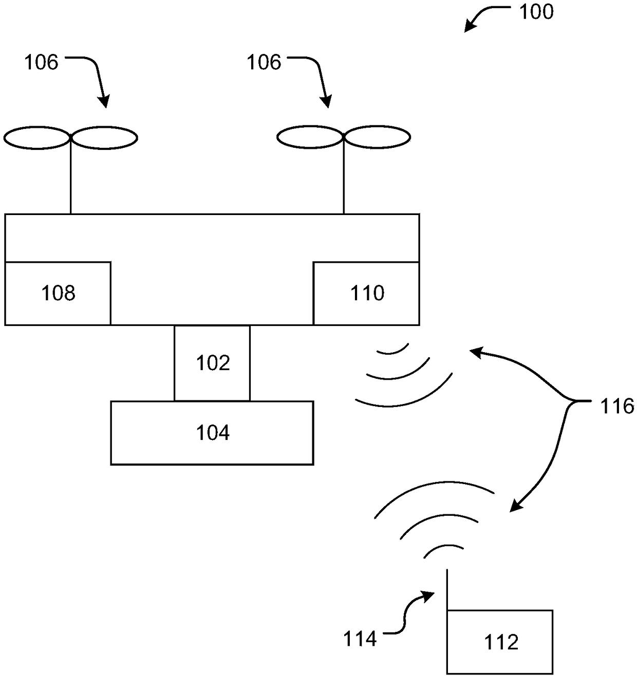
[0034] see figure 2 , a UAV return path planning method provided by an embodiment of the present invention. Wherein, the method can be implemented by a dedicated control device mounted on the UAV 100 , or by a flight controller of the UAV 100 .

[0035] The following will take the flight controller as the execution subject to further illustrate the specific process of the UAV return path planning method in the embodiment of the present invention.

[0036] see figure 2 , the method may include the following steps:

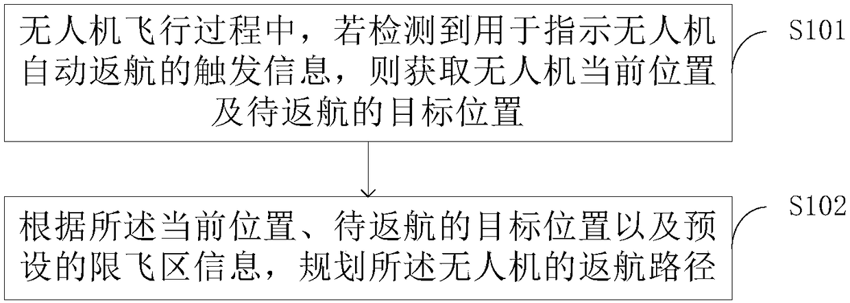
[0037] Step S101: During the flight of the UAV 100, if the trigger information for instructing the UAV 100 to automatically return is detected, the current position of the UAV 100 and the target position to be returned are obtained;

[0038] In this embodiment, the trigger information indicates that the UAV 100 is out of control. The reasons for causing the unmanned aircraft to be out of control may be machine failures, environmental factors (such as interfere...

Embodiment 2

[0068] Corresponding to the UAV return path planning method described in Embodiment 1, the embodiment of the present invention provides a UAV return path planning device.

[0069] see Figure 5 , the UAV return path planning device may include a processor 11, wherein the processor 11 is configured to execute the steps of the UAV return path planning method described in the first embodiment above.

[0070] In this embodiment, the processor 11 may be selected as a controller in a dedicated control device, may also be selected as a flight controller of the UAV 100, or may be selected as a pan-tilt controller.

[0071] For the unexpanded parts, please refer to the same or similar parts of the UAV return path planning method in the first embodiment above, and will not be repeated here.

Embodiment 3

[0073] Corresponding to the UAV return path planning method described in Embodiment 1, the embodiment of the present invention provides a UAV return path planning device.

[0074] see Figure 6 , the UAV return path planning device may include:

[0075] The detection module 10, during the flight of the UAV 100, detects whether there is trigger information for instructing the UAV 100 to return automatically;

[0076] The acquisition module 20 is used to acquire the current position of the drone 100 and the target position to be returned after the detection module 10 detects the trigger information for instructing the automatic return of the drone 100;

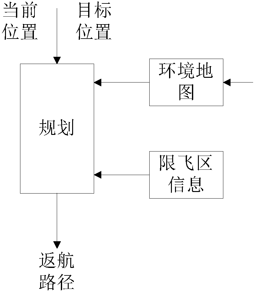
[0077] The planning module 30 is configured to plan the return route of the UAV 100 according to the current position, the target position to be returned and the preset restricted-fly zone information.

[0078] Further, the target position to be returned is a preset specific position; or, the target position to be returned is ...


PUM


Abstract

An unmanned aerial vehicle (100) return path planning method and device are disclosed. The return path planning method comprises the steps of obtaining the current position, the target position to bereturned and preset flying limit area information of the unmanned aerial vehicle (100) if the triggering information used for indicating that the unmanned aerial vehicle automatically returns in the flying process of the unmanned aerial vehicle (100) (s101);and planning a return path of the unmanned aerial vehicle (s102) according to the current position, the target position to be returned and preset flying limit area information. The influence of the flying limit area is considered when automatic return path of the unmanned aerial vehicle is planned, so that the unmanned aerial vehicle can besafely returned after the unmanned aerial vehicle is out of control. The unmanned aerial vehicle can be prevented return failure of the unmanned aerial vehicle due to the unmanned aerial vehicle falling into a flying limit area and being clamped at the edge of the flying limit area.

Description

technical field [0001] The invention relates to the field of unmanned aerial vehicles, in particular to a method and device for planning a return path of an unmanned aerial vehicle. Background technique [0002] At present, the automatic return of the UAV does not plan the return path in advance. This type of return usually returns directly from the return altitude to the target position after selecting a return altitude. The above drone return strategy does not consider the impact of the restricted flight zone. During the return process, the drone may be hindered by the restricted flight zone, resulting in the failure of the return flight and being stuck on the edge of the restricted flight zone. Contents of the invention [0003] The present invention provides a UAV return path planning method and device. [0004] According to a first aspect of the present invention, a method for planning a UAV return route is provided, the method comprising: [0005] During the flight...

Claims


Application Information

Patent Timeline
Patent Type & Authority Applications(China)
IPC IPC(8): G05D1/10
CPCG05D1/101G05D1/106
Inventor 张立天耿畅
Owner SZ DJI TECH CO LTD
Why Eureka
Try Eureka