

Pipe cutting device
A technology for cutting devices and pipes, which is applied to sawing machines, attachments of sawing machines, metal sawing equipment, etc., can solve the problems of increasing the labor intensity of operators, complicated cutting processes, and low work efficiency, so as to ensure fixed-length cutting. , novel structure, high work efficiency
Active Publication Date: 2019-04-09
安徽酷勒威拉丝模有限公司
View PDF8 Cites 1 Cited by
- Summary
- Abstract
- Description
- Claims
- Application Information
AI Technical Summary
Problems solved by technology
When cutting in this way, the steel pipe needs to be pre-clamped, and the steel pipe needs to be loosened when the steel pipe is removed. The whole cutting process is complicated, which increases the labor intensity of the operator, and the work efficiency is low.
Method used
View moreImage
Smart ImageViewing Examples

Examples
Embodiment Construction
[0015] The present invention will be described in further detail below by means of specific embodiments:
Login to View More PUM
 Abstract
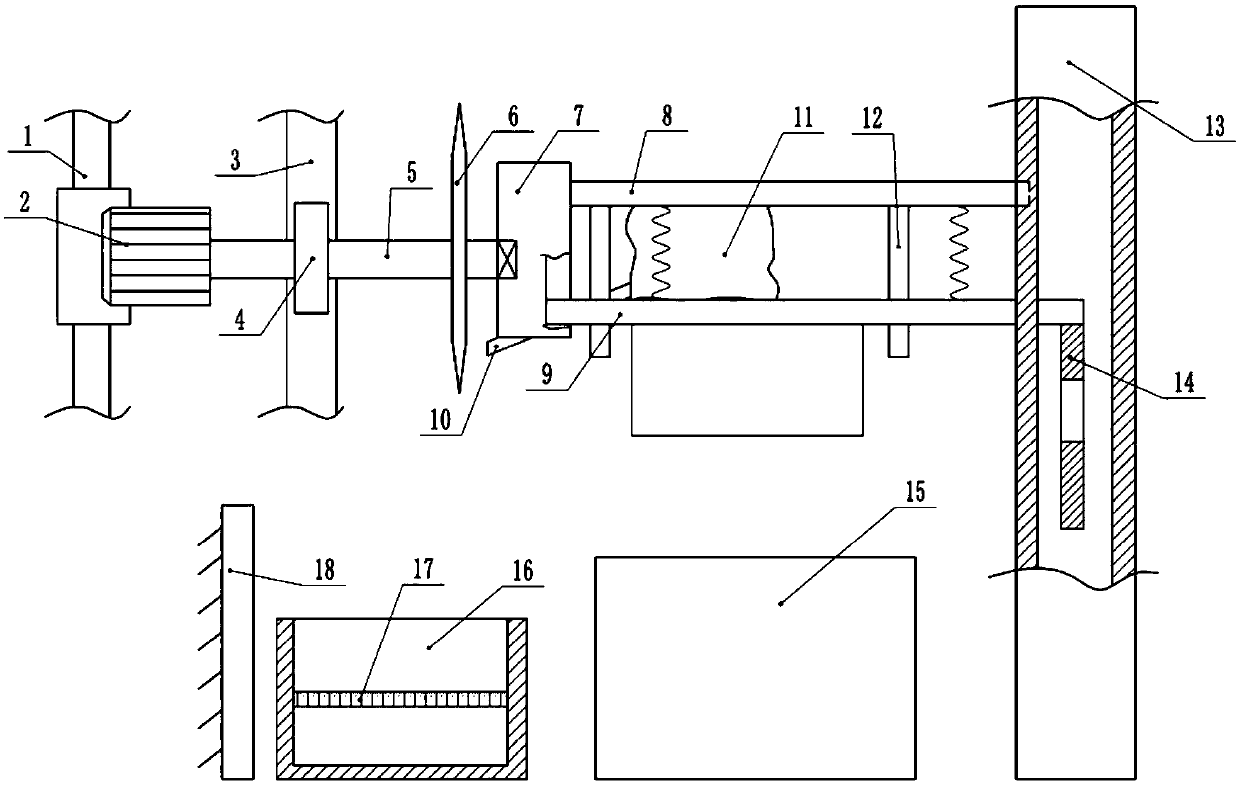
The invention belongs to the technical field of cutting equipment, and particularly discloses a pipe cutting device. The pipe cutting device comprises a sliding rail and a motor in sliding connectionwith the sliding rail. A transmission gear and a rotating shaft are connected to an output shaft of the motor, a machine frame is provided with a rack engaged with the transmission gear, a cutting sawblade is fixedly connected to the rotating shaft, and a sliding plate is rotationally connected to the end of the rotating shaft. A fixed plate is arranged on the right of the sliding plate, a lifting plate is arranged between the sliding plate and the fixed plate, a clamping plate is arranged below the lifting plate, the two ends of the clamping plate are in sliding connection with the sliding plate and the fixed plate correspondingly, a water bag is arranged between the lifting plate and the clamping plate, and the water bag is connected with a water pipe. A push plate with a through hole is in sliding connection with the interior of the fixed plate, the push plate is fixedly connected with the clamping plate, a base is arranged below the clamping plate, and one side of the base is provided with a trough and a baffle. A steel pipe is rapidly cut, and working efficiency is improved.
Description
technical field [0001] The invention belongs to the technical field of cutting equipment, and in particular relates to a pipe material cutting device. Background technique [0002] At present, due to the simple, convenient and fast process of steel processing and production, construction and installation, it has become an important material component required in various fields and is widely used in various fields of national economic construction; especially steel pipes, in our industrial production The application is more and more extensive. Now in the production of automobiles, steel pipes are also an indispensable material, and steel pipes for automobiles are used as the necessary connection and fixing parts for the parts produced by automobiles. [0003] At present, in the production process of the enterprise, when the steel pipe is too long to affect the use, it is necessary to cut the steel pipe. In the prior art, one of the methods for cutting steel pipes is by manu...
Claims
Login to View More Application Information
Patent Timeline
 Patent Type & AuthorityPatents(China)
IPC IPC(8): B23D45/02B23D45/12B23D47/04B23D47/08B23D59/00B23D59/02
CPCB23D45/022B23D45/12B23D47/04B23D47/08B23D59/001B23D59/02
Inventor李志华
Owner安徽酷勒威拉丝模有限公司