Automatic printing device

A technology of automatic printing and the first printing roller, which is applied in the direction of printing device, printing, printing machine, etc., can solve the problems of ink waste, inconvenient printing of pending printed matter, and difficulty in adjusting the speed of two printing rollers, etc.

Inactive Publication Date: 2018-09-07
重庆川之舟印务设计有限公司
View PDF0 Cites 0 Cited by
  • Summary
  • Abstract
  • Description
  • Claims
  • Application Information

AI Technical Summary

Problems solved by technology

However, due to the high speed of rotation of the printing roller, when the printing roller rotates at a high speed, the printing roller and the ink in the ink tank collide with each other, thereby easily causing the ink in the ink tank to splash.
Moreover, when the printing roller is just dipped in ink, there is more ink, and the printing roller rotating at a high speed will easily throw off the dipped ink.
Therefore, the existing ink filling method of the printing roller is easy to cause the ink to splash or be thrown off by the printing roller, resulting in waste of ink and inconvenience to the printing of the to-be-printed matter
[0004] Moreover, the current traditional printing device can only print thinner and flat surface to be printed
When the material to be printed is thick and the surface of the material to be printed is a curved surface, such as a curved cardboard, due to the curvature of the material to be printed, it is necessary to make the rotation speeds of the two printing rollers that are attached to the material to be printed different, but the existing printing device, The rotational speeds of the two printing rollers are the same, and it is not easy to adjust the rotational speeds of the two printing rollers. Therefore, the existing printing device cannot print the curved and thicker to-be-printed products

Method used


Image

  • Automatic printing device
  • Automatic printing device
  • Automatic printing device

Examples


Embodiment Construction

[0018] The following is further described in detail through specific implementation methods:

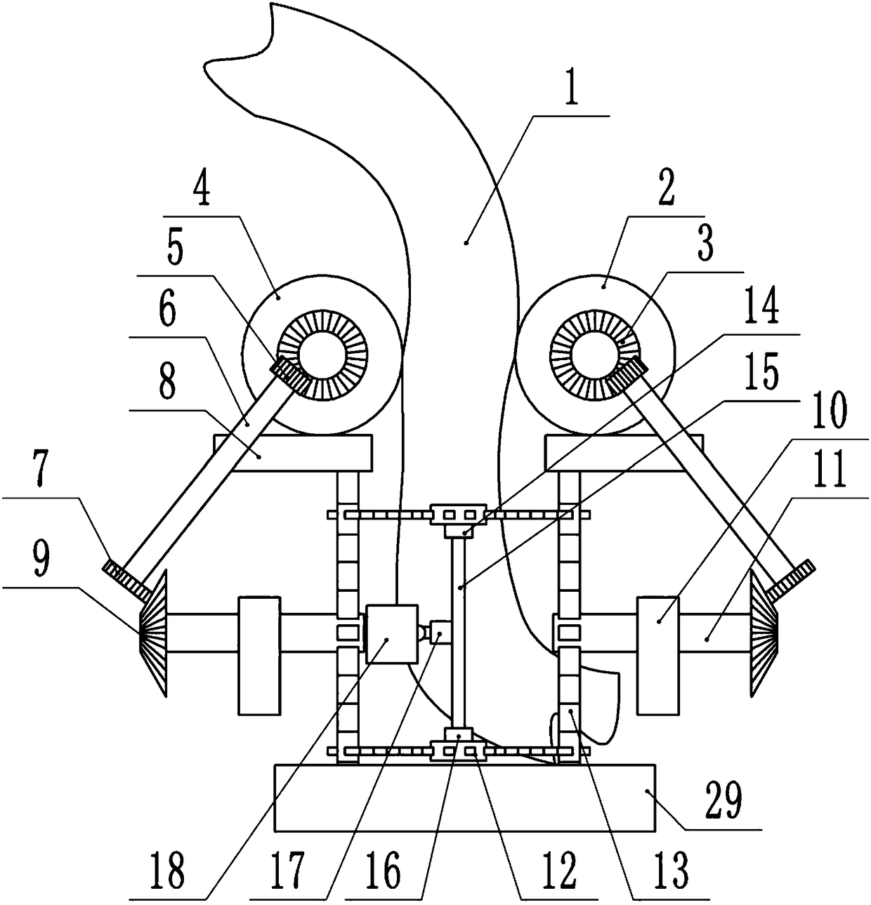
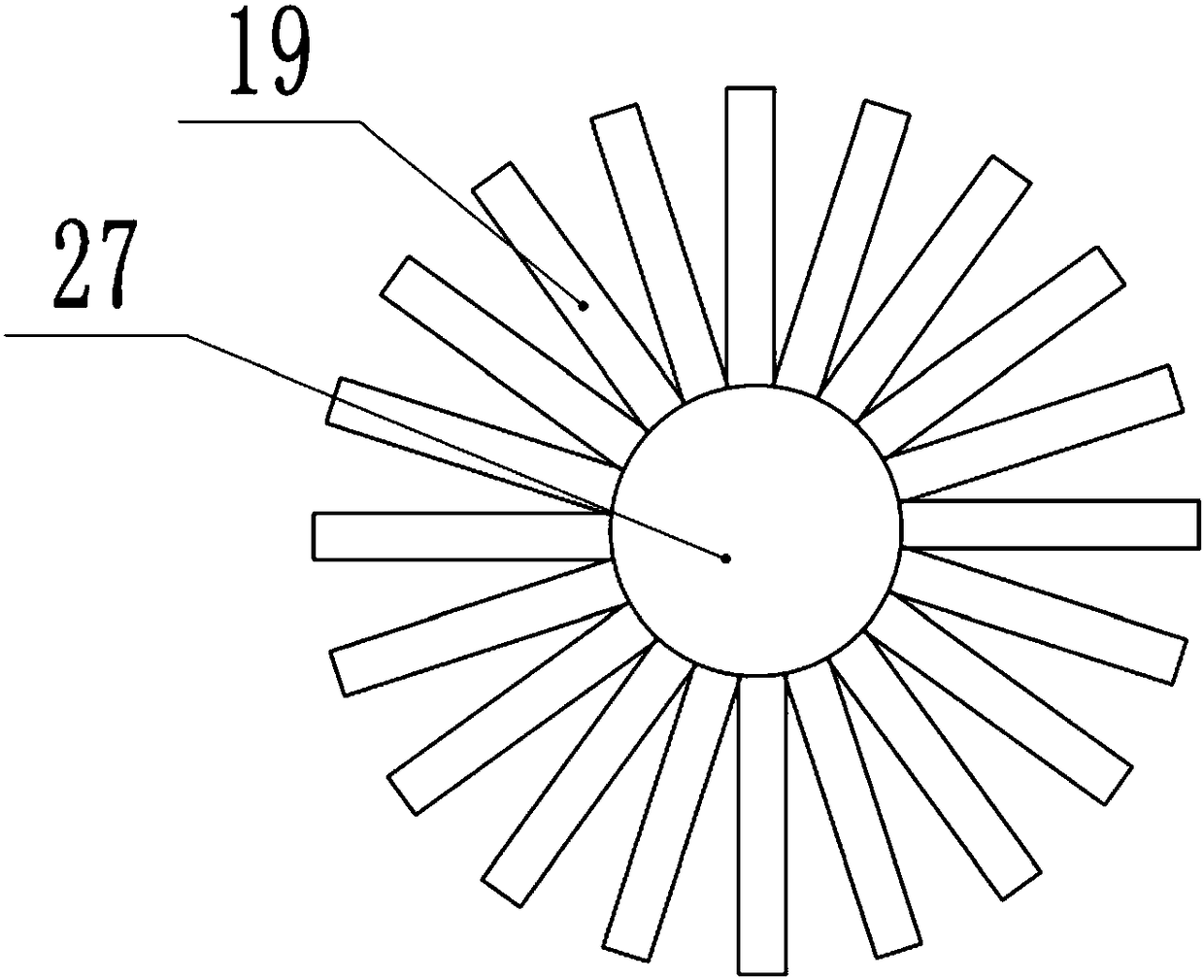
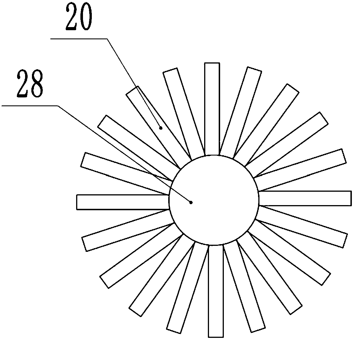
[0019] The reference signs in the accompanying drawings of the description include: the product to be printed 1, the first printing roller 2, the fourth helical gear 3, the second printing roller 4, the second helical gear 5, the linkage shaft 6, the first helical gear 7, the sponge block 8. The third helical gear 9, fixed block 10, rotating shaft 11, planetary rotating member 12, transmission rotating member 13, first bearing 14, connecting shaft 15, second bearing 16, connecting block 17, motor 18, transmission rotating rod 19 , planetary rotating rod 20, dividing plate 21, piston head 22, spring 23, roller 24, weight 25, stay cord 26, transmission rotating ring 27, planetary rotating ring 28, ink tank 29.

[0020] The embodiment is basically as attached Figure 1-Figure 4 Shown: an automatic printing device, including a frame, on which a first printing roller 2 and a second print...


PUM


Abstract

The invention relates to an automatic printing device which comprises a rack. A first printing roller and a second printing roller are rotatably connected to the rack, and the side face of the first printing roller and the side face of the second printing roller are both slidably connected with ink suction blocks; two fixing blocks are connected to the rack and both rotatably connected with rotating shafts, the ends, close to each other, of the two rotating shafts are both connected with transmission rotating pieces, and an ink tank is arranged on the lower portions of the transmission rotating pieces; two directly facing planetary rotating pieces are engaged between the two transmission rotating pieces, and a connecting shaft is arranged between the two planetary rotating pieces; the twoends of the connecting shaft are rotatably connected with a first rotating part and a second rotating part correspondingly, and the first rotating part and the second rotating part are fixedly connected with the two planetary rotating pieces correspondingly; the middle of the connecting shaft is connected with a driving mechanism enabling the connecting shaft to rotate, and linkage mechanisms areconnected between the ends, away from the transmission rotating pieces, of the two rotating shafts and the first printing roller as well as between the between the ends, away from the transmission rotating pieces, of the two rotating shafts and the second printing roller correspondingly. According to the automatic printing device, a to-be-printed object with the bent surface and the large thickness is printed.

Description

technical field [0001] The invention relates to the technical field of printing, in particular to an automatic printing device. Background technique [0002] Printing is the process of transferring text, pictures, photos, anti-counterfeiting and other originals through plate making, ink application, pressurization, etc., so that the ink is transferred to the surface of the material to be printed (paper, fabric, plastic, leather, etc.), and the content of the original is copied in batches. . [0003] In the printing process, the printed matter needs to be printed on both sides, so the printed matter is clamped by two printing rollers. On the one hand, the printing roller rotates to convey the printed matter forward, and on the other hand, the printing roller applies ink to the printed matter. Thereby printing is realized. Wherein, the inking method of the printing roller is inked in the following way: other parts of the side of the printing roller are immersed in the ink ta...

Claims


Application Information

Patent Timeline
IPC IPC(8): B41F17/00
CPCB41F17/00B41P2217/50
Inventor 杨学智
Owner 重庆川之舟印务设计有限公司
Why Eureka
Try Eureka