Locking mechanism for hub bearing and use method thereof

A locking mechanism and wheel bearing technology, applied in the direction of wheel hub, transportation and packaging, vehicle parts, etc., can solve the problems of vehicle performance and safety impact, inconvenient maintenance, large fluctuation of preload force, etc., and achieve relative positional relationship. Stable, easy maintenance, flexible disassembly and assembly

Inactive Publication Date: 2018-09-07
ANHUI JIANGHUAI AUTOMOBILE GRP CORP LTD
View PDF6 Cites 1 Cited by
  • Summary
  • Abstract
  • Description
  • Claims
  • Application Information

AI Technical Summary

Problems solved by technology

[0005] 1. The wheel hub bearings of large vehicles are relatively large, and the lock nuts required are large in size and pre-tightening force. They need to be assembled by a special nut tightening machine. When repairing the wheel hub bearings, it is difficult to disassemble and assemble the lock nuts, and the maintenance is inconvenient
[0006] 2. The lock nut of a large vehicle requires a large pre-tightening force. If there is no special equipment, it is difficult to control the pre-tightening force accuracy:
[0007] a) The pre-tightening force is lower than the specified value, the lock nut is easy to loosen, the outer hub bearing and the inner hub bearing will shake along the steering knuckle shaft after losing their fixation, and the bearings will wear quickly
[0008] b) The pre-tightening force is higher than the specified value, and the lock nut presses the outer wheel hub bearing and the inner wheel hub bearing too tightly, causing the bearings to wear quickly, easy to heat up and ablate, and the rotation resistance is large, the driving resistance of the vehicle is large, and the fuel consumption is high
[0009] Therefore, for larger lock nuts, the pre-tightening force fluctuates greatly during actual operation, which is difficult to control accurately, and the performance and safety of the vehicle are affected

Method used


Image

  • Locking mechanism for hub bearing and use method thereof
  • Locking mechanism for hub bearing and use method thereof
  • Locking mechanism for hub bearing and use method thereof

Examples


Embodiment Construction

[0046] The embodiments described below by referring to the figures are exemplary only for explaining the present invention and should not be construed as limiting the present invention.

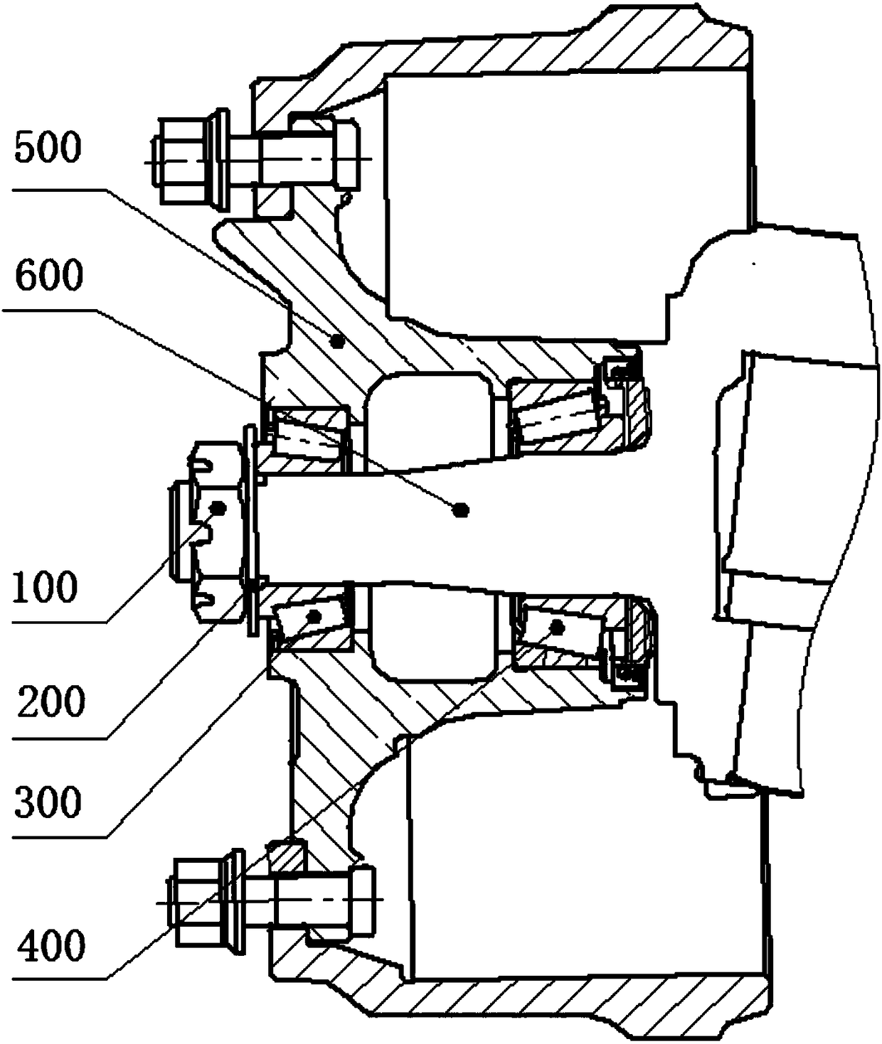
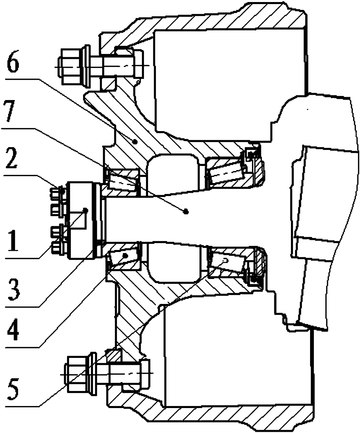
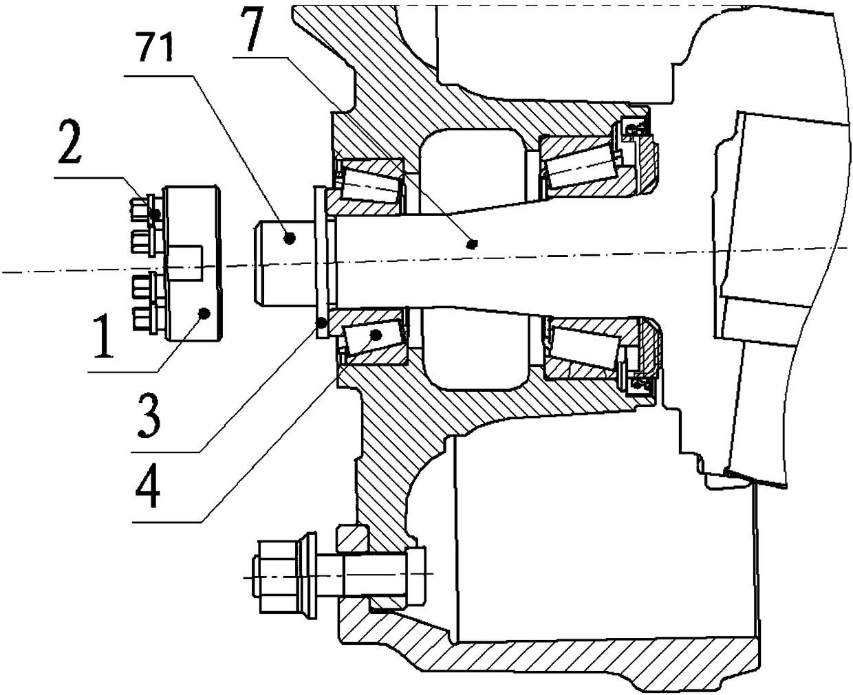
[0047] Such as Figure 2 to Figure 6 As shown, the embodiment of the present invention provides a locking mechanism for hub bearings, including a steering knuckle 7, the steering knuckle 7 has a rotating shaft 71, and the inner hub bearing 5, The hub 6, the outer hub bearing 4, the outer circumference of the end of the rotating shaft 71 is distributed with external threads, and also includes a lock nut 1 and a push bolt 2, the lock nut 1 has a threaded hole 101, and the lock nut 1 is connected to the rotating shaft through the threaded hole 101 The outer circumference of 71 is threaded; the edge of the lock nut 1 is provided with several mounting holes 102 in the axial direction, and the mounting holes 102 are arranged in a circular array with the threaded hole 101 as the center; the number o...


PUM


Abstract

The invention discloses a locking mechanism for a hub bearing and a use method thereof. As a mounting hole and a pushing bolt connected with a locking nut via threads are arranged in the circumferential direction of the locking nut, and the axis extension line of the pushing bolt penetrates through the inner ring of an external hub bearing, the pushing bolt can be made to prop against the inner ring of the external hub bearing by tightening the locking nut first and then tightening the pushing bolt; after a pretightening force is reached, the pushing bolt can suffer a reverse acting force of the inner ring of the external hub bearing so that the locking nut indirectly bears the force, and therefore, the thread clearance between the locking nut and a steering knuckle is reduced and the relative position relation between the locking nut and the external hub bearing is kept stable; the tightening operation of the locking nut and assembling and disassembling operations of the pushing boltare comparatively flexible without using special equipment so that the the maintenance is convenient, the pretightening force of the locking nut is convenient to control and the anti-loosening effectof the locking nut is enhanced; and as the pushing bolt is in contact with the inner ring of the external hub bearing, the running of the hub bearing is not affected.

Description

technical field [0001] The invention relates to a locking mechanism, in particular to a locking mechanism for a hub bearing and a usage method thereof. Background technique [0002] The hub of the automobile wheel and the steering knuckle are supported by the hub bearing. When the vehicle is running, the wheel hub rotates around the hub bearing, and the weight carried by the wheel is transmitted to the steering knuckle through the hub bearing. The hub bearing is usually pressed on the steering knuckle with a lock nut according to a precise preload. If the pre-tightening force is too small, the nuts are easy to loosen, which will cause the internal clearance of the hub bearing to be large and loose, the bearing will wear quickly, and the wheel hub will shake, which will affect the driving stability of the vehicle; if the pre-tightening force is too large, the hub bearing will be pressed too tightly. The internal wear of the bearing is fast, easy to generate heat and ablation...

Claims


Application Information

Patent Timeline
Patent Type & Authority Applications(China)
IPC IPC(8): B60B27/00B60B27/02
CPCB60B27/0078B60B27/02
Inventor 李刚姚英
Owner ANHUI JIANGHUAI AUTOMOBILE GRP CORP LTD
Why Eureka
Try Eureka