
motorcycle

A technology for motorcycles and vehicles, applied in the directions of motorcycles, motor vehicles, bicycles, etc., can solve the problem of rightward rotation of the steering shaft

Active Publication Date: 2020-03-13
YAMAHA MOTOR CO LTD
View PDF7 Cites 0 Cited by
  • Summary
  • Abstract
  • Description
  • Claims
  • Application Information

AI Technical Summary

Problems solved by technology

Therefore, the steering shaft may rotate to the right

Method used


Image

  • motorcycle
  • motorcycle
  • motorcycle

Examples


no. 1 example

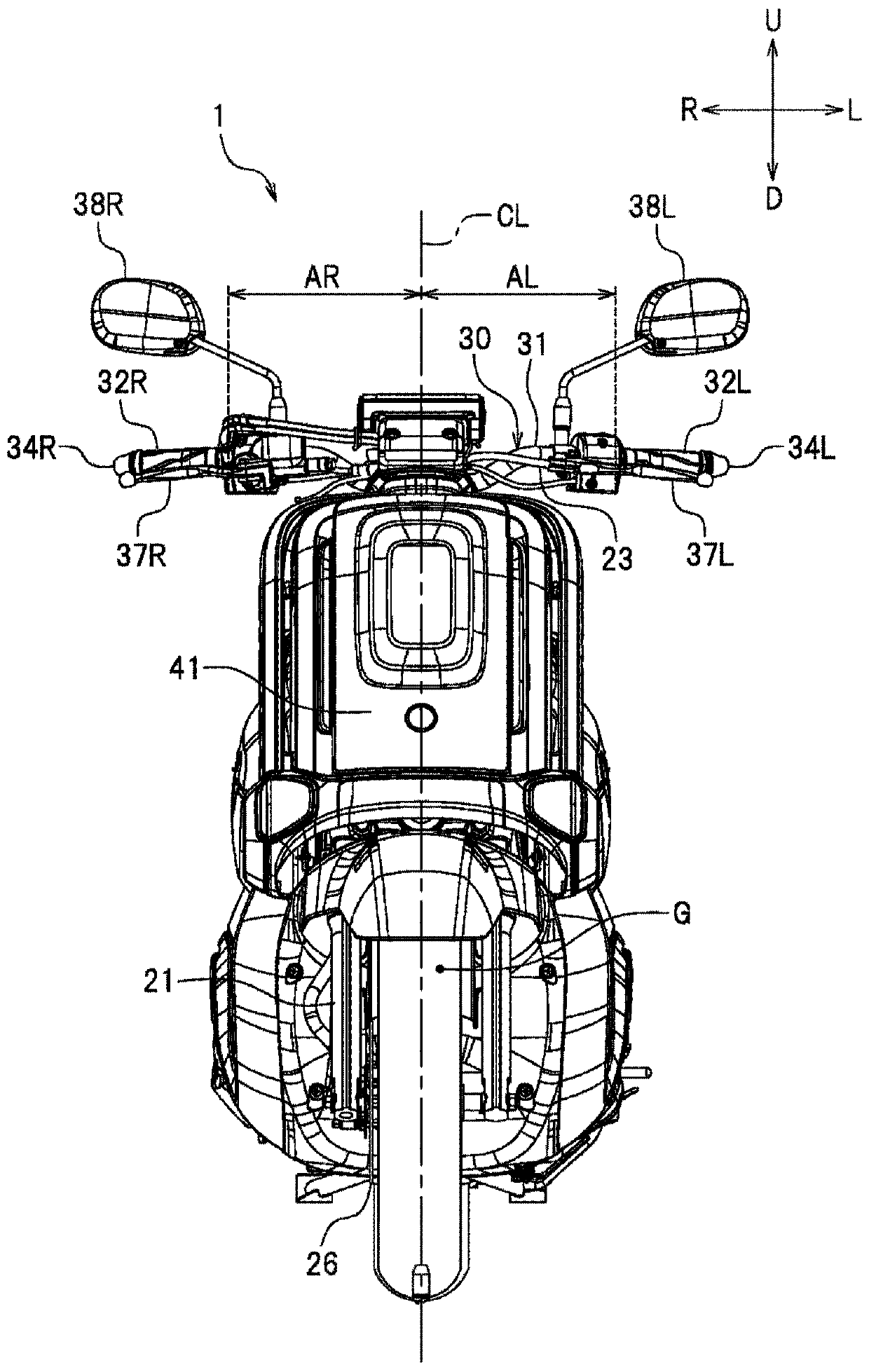
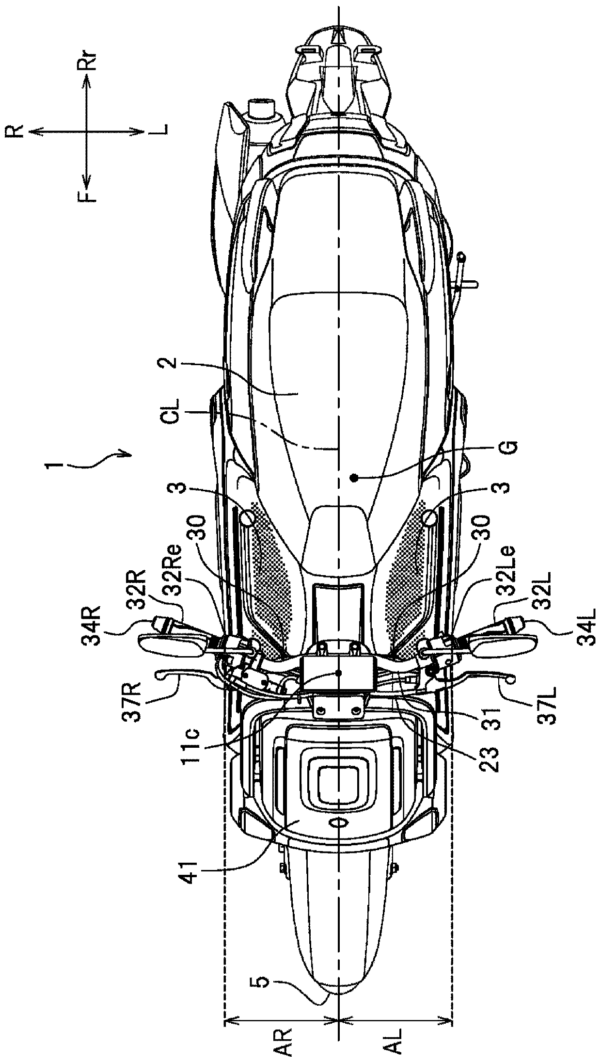
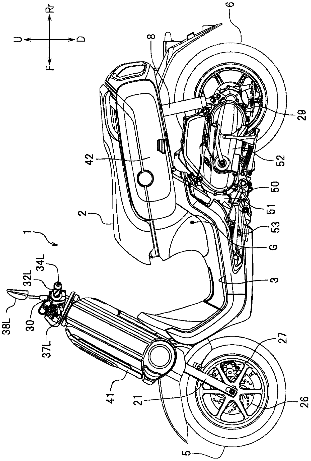
[0048] Preferred embodiments will now be described with reference to the accompanying drawings. figure 1 is a front view of a motorcycle 1 according to a preferred embodiment. figure 2 is a top view of motorcycle 1, image 3 is the left side view of motorcycle 1.

[0049] The terms front, rear, left, right, up and down used in the following description of the construction of the motorcycle 1 refer to the direction from the seat when the motorcycle 1 stands on a horizontal surface with no load thereon. These directions are seen by the virtual cyclist on chair 2. The term unladen means that the motorcycle 1 has no fuel, and no luggage mounted on it, and no rider. The designations F, Rr, L, R, U, and D used in the figures refer to front, back, left, right, top, and bottom, respectively.

[0050] The motorcycle 1 of this embodiment is a scooter type motorcycle. However, the motorcycle of the present teaching is not limited to the scooter type motorcycle. Such as Figure 4 ...

no. 2 example

[0075] In the first embodiment, when the vehicle is viewed from above, the center of gravity G of the vehicle is located on the left side of the vehicle center line CL, and the brake 25 is located on the right side of the front wheels 5 . However, when the vehicle is viewed from above, the center of gravity G of the vehicle may be located on the right side of the vehicle center line CL, and the brake 25 may be located on the left side of the front wheels 5 (see Figure 12 ). A distance AR in the vehicle width direction between the left end 32Re of the right grip 32R and the vehicle center line CL is greater than a distance B in the vehicle width direction between the right end 25e of the brake 25 and the vehicle center line CL. In this case, the weight of the handle right end 30R can be made larger than the weight of the handle left end 30L. Thus, it is possible to suppress the steering shaft 20 from easily rotating to the left. Accordingly, when the vehicle body frame 10 fa...


PUM


Abstract

The invention discloses a motorcycle. The invention improves the straight running stability while suppressing the weight increase of the motorcycle. The center of gravity of the motorcycle deviates from the center line of the vehicle to the left and the brake of the motorcycle is located on the right side of the front wheel, or the center of gravity of the motorcycle deviates from the center line of the vehicle and the motorcycle The brake is located on the left side of the front wheel. When the vehicle is viewed from above, the center of gravity G of the vehicle is located on the left side of the vehicle center line CL. The brake is located on the right side of the front wheel 5. The distance AL in the vehicle width direction between the right end 32Le of the left grip 32L and the vehicle center line CL is larger than the distance in the vehicle width direction between the left end of the brake and the vehicle center line CL. The weight of the portion of the handle 30 located to the left of the right end 32Le of the left grip 32L is greater than the weight of the portion of the handle 30 located to the right of the left end 32Re of the right grip 32R.

Description

technical field [0001] The invention relates to a motorcycle. Background technique [0002] For example, a method described in Japanese Utility Model No. 2537734 is known in the art as a method for adjusting the position of the center of gravity of a motorcycle in the vehicle width direction. Japanese Utility Model No. 2537734 discloses a motorcycle which makes the center of gravity close to the center line of the vehicle by designing the arrangement of relatively heavy vehicle components. In the motorcycle disclosed in Japanese Utility Model No. 2537734, the gearbox is located on the left side of the vehicle center line, and the muffler is located on the right side of the vehicle center line. By arranging the battery case on the right side of the vehicle center line, the left-right balance of the vehicle as a whole is ensured. [0003] By ensuring the right-to-left balance, the straight-line stability of the motorcycle can be improved. However, in order to bring the cent...

Claims


Application Information

Patent Timeline
Patent Type & Authority Patents(China)
IPC IPC(8): B62K11/14B62K21/26
CPCB62K11/14B62K21/26B62L1/00B62K21/12B62K21/125
Inventor 竹迫和平水野良太
Owner YAMAHA MOTOR CO LTD
Learn More