
Double-layer mutual-capacitance touch panel

A touch panel, mutual capacitance technology, applied in the field of double-layer mutual capacitance touch panel, can solve the problem that the range wire 26 cannot be reduced, and achieve the effect of reducing the width of the peripheral area

Active Publication Date: 2018-09-07
ILI TECHNOLOGY CORPORATION
View PDF13 Cites 2 Cited by
  • Summary
  • Abstract
  • Description
  • Claims
  • Application Information

AI Technical Summary

Problems solved by technology

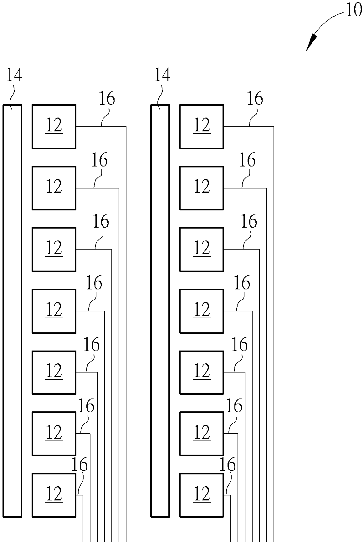
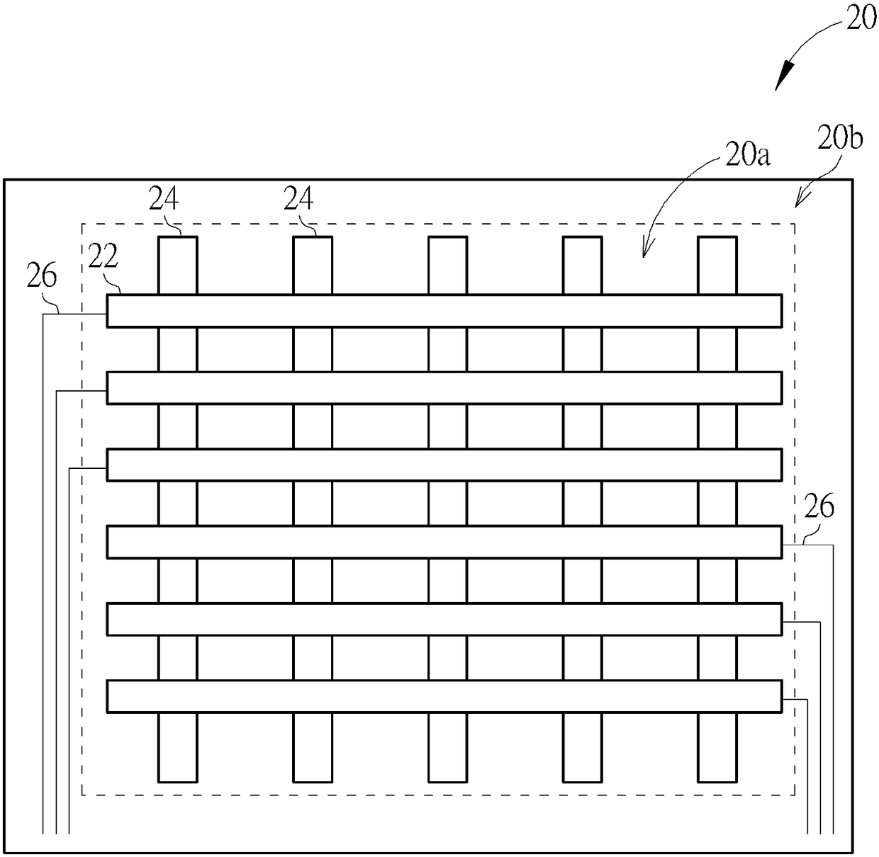
However, in the design of the conventional double-layer electrode structure, the wires 26 for electrically connecting the sensing electrodes 22 to the pads are arranged in the peripheral regions 20b on both sides of the touch region 20a, so that the peripheral region 20b range will be limited by the number of wires 26 and cannot be reduced

Method used


Image

  • Double-layer mutual-capacitance touch panel
  • Double-layer mutual-capacitance touch panel
  • Double-layer mutual-capacitance touch panel

Examples


no. 1 example

[0049] In another variant embodiment, such as Figure 5 As shown, when N is equal to 3, each row of the array includes not only the first electrode series 110 and the second electrode series 112 , but also the third electrode series 128 . For clarity, Figure 5 Only a single row is displayed, but not limited to. Compared with the first embodiment, in the first conductive layer C1a of this variant embodiment, the electrodes E1 located in 3*M-1 columns are electrically connected to each other to form a first electrode series 110a, and the electrodes located in 3*M columns E2 are electrically connected to each other to form a second electrode series 112a, and electrodes E3 located in 3*M-2 columns are electrically connected to each other to form a third electrode series 128, wherein the first electrode series 110a, the second electrode series 112a and the third electrode series 128 are insulated from each other. Each first wire 120 is electrically connected to each first elect...


PUM


Abstract

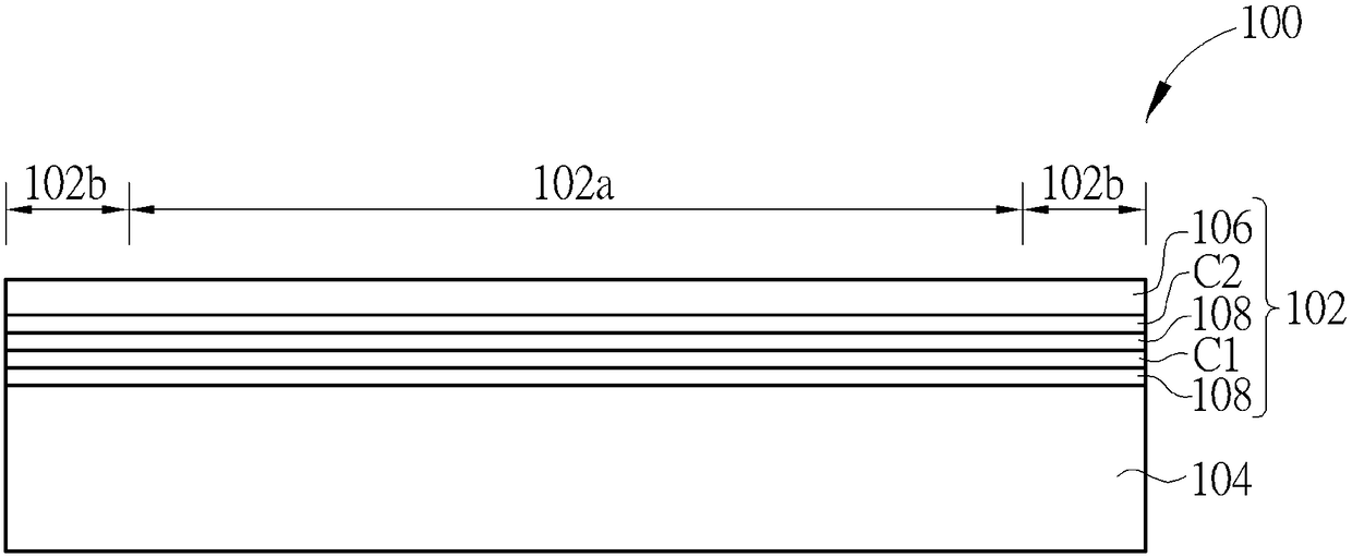
The invention provides a double-layer mutual-capacitance touch panel. The touch panel comprises a first conducting layer and a second conducting layer. The first conducting layer comprises multiple electrodes which are arranged in an array, wherein in each row of the array, the electrodes located in the (N*M)-1 column are mutually electrically connected into a first electrode string row, the electrodes located in the N*M column are mutually electrically connected into a second electrode string row, N is a positive integer greater than or equal to 2, and M is a positive integer greater than orequal to 1. The second conducting layer comprises M mutually insulated electrode strip groups which are sequentially arranged along the row direction of the array, wherein each electrode strip group comprises N mutually electrically connected electrode strips, and all the electrode strips in each electrode strip group extend along the column direction of the array and are overlapped with the electrodes in the corresponding column.

Description

technical field [0001] The invention relates to a mutual capacitive touch panel, in particular to a double layer mutual capacitive touch panel with a double layer electrode structure. Background technique [0002] With the rapid development of science and technology, touch display devices composed of displays and touch panels can realize touch and display functions at the same time, and have the characteristics of human-computer interaction, and have been widely used in smart phones (smart phones), satellites, etc. Navigation system (GPS navigator system), tablet computer (tablet PC) and notebook computer (laptopPC) and other electronic products. Among them, the mutual capacitive touch panel has become the mainstream touch technology used in the industry due to its advantages of high accuracy, multi-touch, high durability, and high touch resolution. [0003] The mutual capacitive touch technology mainly detects the touch event by detecting the change of coupling capacitance...

Claims


Application Information

Patent Timeline
Patent Type & Authority Applications(China)
IPC IPC(8): G06F3/044
CPCG06F3/044
Inventor 詹秉燏
Owner ILI TECHNOLOGY CORPORATION
Learn More