
Touch display panel and touch display device

A touch display panel and display panel technology, which is applied in the directions of instruments, calculations, electrical digital data processing, etc., can solve problems such as poor grounding, large influence of detection signals, and failure to detect touch points normally, so as to reduce parasitic capacitance, The effect of reducing the sensing area

Active Publication Date: 2021-07-30
SHANGHAI TIANMA MICRO ELECTRONICS CO LTD
View PDF4 Cites 0 Cited by
  • Summary
  • Abstract
  • Description
  • Claims
  • Application Information

AI Technical Summary

Problems solved by technology

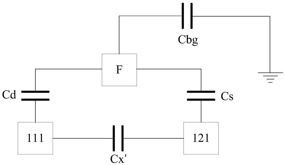
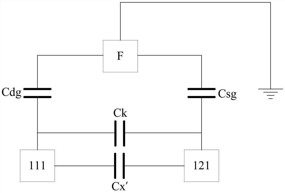
[0004] However, when the touch display panel is in a floating state, that is, the touch display panel is not grounded, and the person is also in a state of poor grounding. The influence of capacitance on the detection signal becomes larger, which may cause the detected signal to exceed the normal detection range, so that the touch point cannot be detected normally
However, the smaller the distance between the finger and the touch electrodes (the driving electrode and the sensing electrode), the greater the influence of the parasitic capacitance formed between the finger and the touch electrode on the detection signal. As a result, in the floating state, the touch display panel cannot Increased probability of normal detection of touch points

Method used


Image

  • Touch display panel and touch display device
  • Touch display panel and touch display device
  • Touch display panel and touch display device

Examples


Embodiment Construction

[0035] Various exemplary embodiments of the present invention will now be described in detail with reference to the accompanying drawings. It should be noted that the relative arrangement of the components and steps, the numerical expressions and numerical values ​​set forth in these embodiments do not limit the scope of the invention unless specifically stated otherwise.

[0036] The following description of at least one exemplary embodiment is merely illustrative in nature and is in no way intended to limit the invention, its application, or uses.

[0037] Techniques, methods, and devices known to those of ordinary skill in the relevant art may not be discussed in detail, but where appropriate, such techniques, methods, and devices should be considered part of the specification.

[0038] In all examples shown and discussed herein, any specific values ​​should be construed as illustrative only and not limiting. Accordingly, other instances of the exemplary embodiment may hav...


PUM

PropertyMeasurementUnit
thicknessaaaaaaaaaa
thicknessaaaaaaaaaa

Abstract

The present invention provides a touch display panel and a touch display device, including: a touch layer, including a first electrode layer and a second electrode layer; the first electrode layer includes at least one first electrode extending along a first direction, including A plurality of first electrode first lines arranged in parallel; the second electrode layer is insulated from the first electrode layer and arranged opposite to the first electrode layer in the third direction, including at least one second electrode extending along the second direction, the second The electrode includes a plurality of second electrode first lines arranged in parallel, the first direction intersects the second direction, and the third direction is perpendicular to the plane where the first electrode layer is located; the first electrode and the second electrode are metal grid electrodes, The extension direction of the first line of the first electrode intersects the extension direction of the first line of the second electrode, and the distance between two adjacent first lines of the first electrode is smaller than the distance between two adjacent first lines of the second electrode the distance between. The invention can reduce the parasitic capacitance between the finger and the touch electrode.

Description

technical field [0001] The present invention relates to the field of display technology, and more particularly, to a touch display panel and a touch display device. Background technique [0002] The touch display panel has both display and touch functions, and the methods for realizing the touch function are mainly divided into resistive type and capacitive type. Among them, the capacitive touch display panel is further divided into two types: self-capacitance type and mutual-capacity type. [0003] For the mutual capacitive touch display panel, touch detection is realized by relying on the change of the capacitance between the driving electrode and the sensing electrode. When a finger touches the surface of the touch display panel, the power on the driving electrodes and the sensing electrodes will change, resulting in a change in the capacitance between the driving electrodes and the sensing electrodes. By detecting this change, it is possible to detect which driver The e...

Claims


Application Information

Patent Timeline
Patent Type & Authority Patents(China)
IPC IPC(8): G06F3/044G06F3/041
CPCG06F3/0416G06F3/044G06F2203/04103
Inventor 谢亮丁洪
Owner SHANGHAI TIANMA MICRO ELECTRONICS CO LTD
Learn More