Rotary positioning support used during instrument and apparatus maintenance

A technology of instrumentation and positioning frame, which is applied to the parts of lighting devices, lighting devices, workbenches, etc. It can solve the problems of difficult to observe the connection points between parts, the inability to turn over and adjust the instrumentation, and reduce the efficiency of maintenance, etc. problems, to achieve the effect of easy flipping, easy maintenance, and improved use effect

Inactive Publication Date: 2018-09-11
HENAN CHANGRUN INSTR
View PDF0 Cites 7 Cited by
  • Summary
  • Abstract
  • Description
  • Claims
  • Application Information

AI Technical Summary

Problems solved by technology

[0003] In the prior art, the height of the maintenance platform of the instrumentation is fixed, and the instrumentation cannot be turned over and adjusted. When the instrumentation is maintained, it is usually necessary to turn over the chassis of the instrumentation several times to repair the upper or lower parts of the chassis. For inspection and maintenance, at present, the turnover of instruments and meters is realized by manually moving and flipping them, which reduces the work efficiency, and because the height of the inspection and maintenance platform is fixed, it is not easy to use for staff with taller or shorter heights. In addition The parts in the existing instruments and meters are small, and it is difficult for the staff to observe the connection points between the parts clearly, which reduces the efficiency of maintenance

Method used


Image

  • Rotary positioning support used during instrument and apparatus maintenance
  • Rotary positioning support used during instrument and apparatus maintenance
  • Rotary positioning support used during instrument and apparatus maintenance

Examples


Embodiment Construction

[0020] In order to make the technical means, creative features, goals and effects achieved by the present invention easy to understand, the present invention will be further described below in conjunction with specific embodiments.

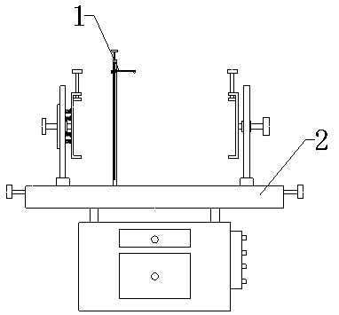
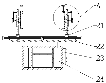
[0021] see Figure 1-Figure 4 , the present invention provides a technical solution: a rotating positioning frame used in the maintenance of instruments and meters, including an auxiliary observation assembly 1 and a positioning assembly 2, and the auxiliary observation assembly 1 is assembled on the rear end of the positioning assembly 2.

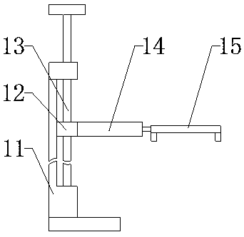
[0022] Auxiliary observation assembly 1 comprises vertical rod 11, bearing seat 12, screw mandrel 13, telescoping rod 14 and magnifying glass 15, and screw mandrel 13 is installed on the upper end of vertical rod 11, and extends to the inside of vertical rod 11, and bearing seat 12 passes through The ball nut pair is installed on the screw rod 13, the bearing seat 12 is assembled on the inner rear wall of the ...


PUM


Abstract

The invention provides a rotary positioning support used during instrument and apparatus maintenance. The rotary positioning support comprises a vertical rod, a first bearing block, a first lead screw, a stretchable rod, a magnifying glass, a bearing block, a bottom frame, an electric cylinder, a supporting frame, a fixing rod, a T-shaped rod and a clamping frame; the first bearing block is installed on the first lead screw through a ball nut pair and is assembled on the back wall of the interior of the vertical rod through a sliding rail, the stretchable rod is arranged at the front end of the first bearing block, the magnifying glass is assembled at the front end of the stretchable rod, and the auxiliary observing function is achieved through the design; and the bottom frame is assembledat the upper end of the electric cylinder, the bearing block is assembled at the upper end of the bottom frame through a sliding rail, the supporting frame is arranged at the upper end of the bearingblock, the clamping frame is installed at the inner end of the supporting frame, the fixing rod is inlaid at the outer end of the clamping frame, the T-shaped rod is assembled at the outer end of thefixing rod and is installed at the outer end of the supporting frame, and height adjustment is achieved through the design. The rotary positioning support is reasonable in structure, instruments andapparatuses can be conveniently overturned, lifting can be adjusted, and observation is facilitated.

Description

technical field [0001] The invention relates to a rotating positioning frame used in the maintenance of instruments and meters, which belongs to the technical field of instrument and meters maintenance. Background technique [0002] Instrumentation is an instrument or device used to detect, measure, observe, and calculate various physical quantities, material components, and physical parameters. Temperature testers, multi-channel temperature recorders, gas detectors, etc. are all instruments. [0003] In the prior art, the height of the maintenance platform of the instrumentation is fixed, and the instrumentation cannot be turned over and adjusted. When the instrumentation is maintained, it is usually necessary to turn over the chassis of the instrumentation several times to repair the upper or lower parts of the chassis. For inspection and maintenance, at present, the turnover of instruments and meters is realized by manually moving and flipping them, which reduces the wor...

Claims


Application Information

Patent Timeline
Patent Type & Authority Applications(China)
IPC IPC(8): B25H1/10B25H1/16F21V33/00
CPCB25H1/10B25H1/16F21V33/00
Inventor 陈国强
Owner HENAN CHANGRUN INSTR
Why Eureka
Try Eureka