Baby hammock with adjustable swing range
An adjustable swing amplitude technology, which is applied in the field of baby hammocks, can solve problems such as the inability to control the swing amplitude of the hammock, and achieve the effect of sleeping comfortably and reducing the burden
- Summary
- Abstract
- Description
- Claims
- Application Information
AI Technical Summary
Problems solved by technology
Method used
Image
Examples
specific Embodiment approach 1
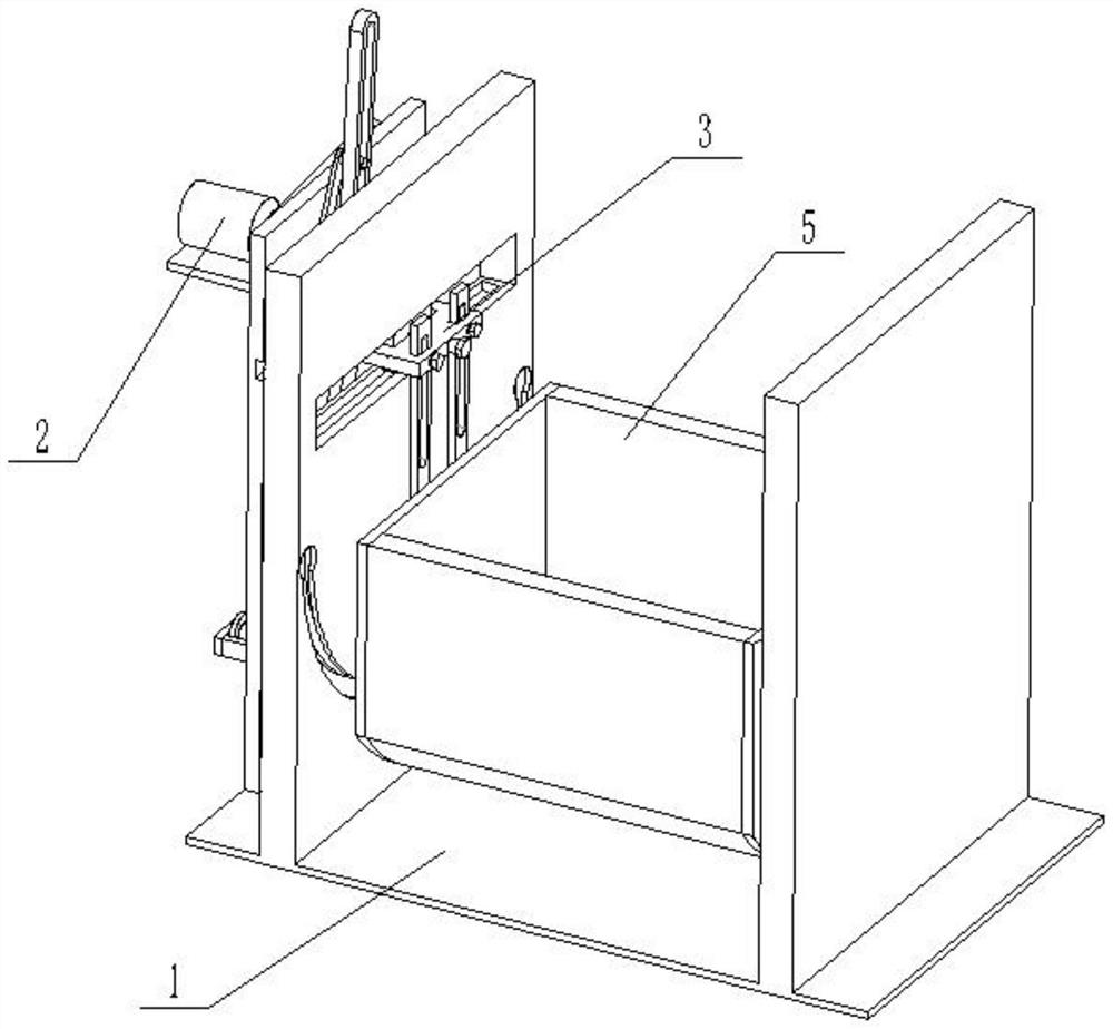
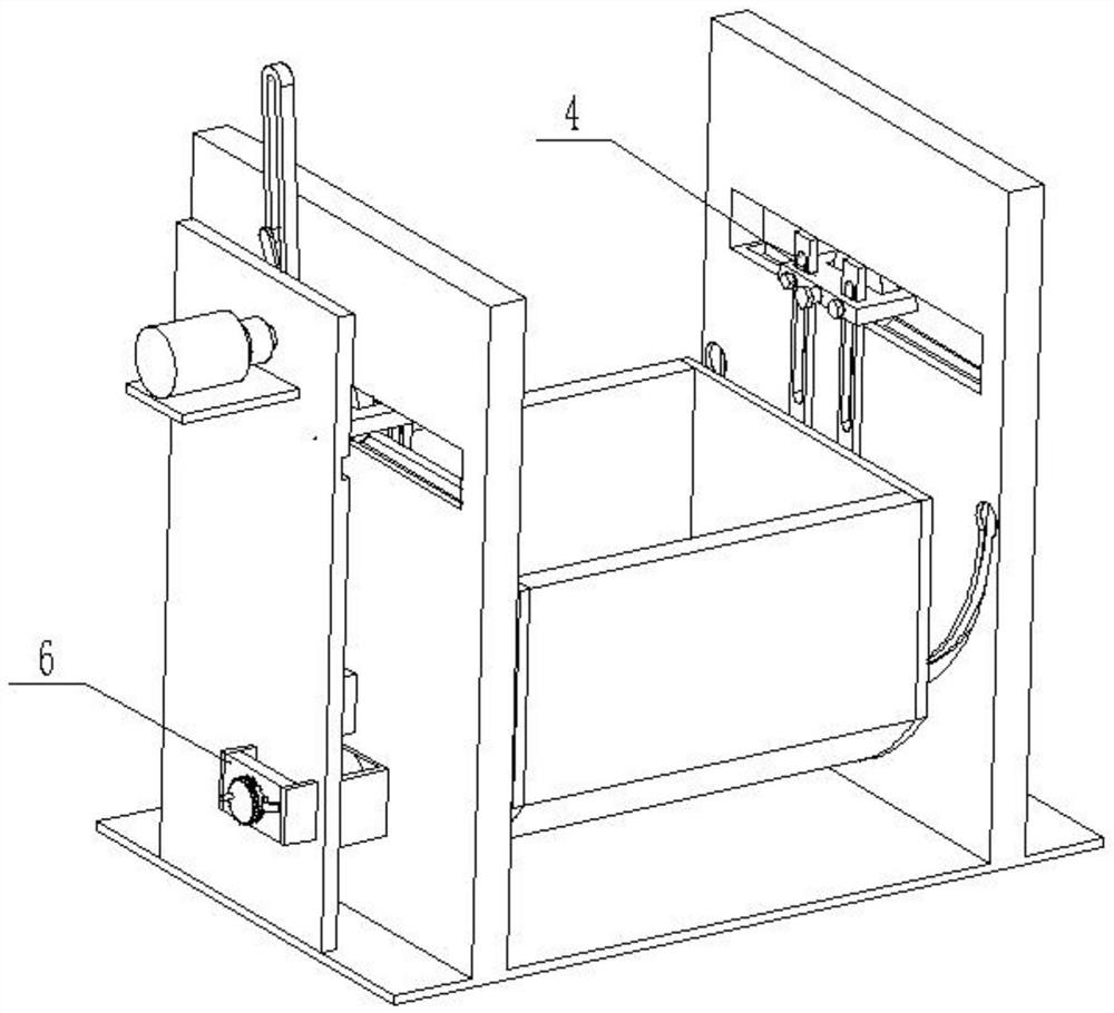
[0026] Such as Figure 1 to Figure 9 As shown, a baby hammock with adjustable swing range includes a base 1, a transmission adjustment structure 2, a main transmission structure 3, a driven structure 4, a baby hammock 5, a protection structure 6 and a driving slider 7. The transmission The adjustment structure 2 is fixedly connected to the left end of the base 1, and two driving sliders 7 are provided. The transmission structure 3, the transmission adjustment structure 2 is slidably connected in the two driving sliders 7, the main transmission structure 3 is slidably connected to the base 1, the right end of the main transmission structure 3 is hinged to the baby hammock 5, and the right end of the baby hammock 5 is hinged to the driven The structure 4 and the driven structure 4 are slidably connected to the base 1 , and the protection structure 6 is plugged into the left end of the base 1 . The transmission adjustment structure 2 drives the main transmission structure 3, the...
specific Embodiment approach 2
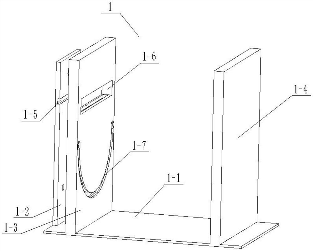
[0028] Such as Figure 1 to Figure 9 As shown, this embodiment further describes the first embodiment, the base 1 includes a bottom plate 1-1, a transmission fixing plate 1-2, a left base plate 1-3, a right base plate 1-4, a horizontal slide Slot 1-5, rectangular through slot 1-6, arc chute 1-7, rectangular slot 1-8, arc chute I 1-9, motor rotation through hole 1-10, adjustment shaft through hole 1- 11 and a rectangular slot 1-12, the transmission fixing plate 1-2 is fixedly connected to the left end of the base plate 1-1, the right base plate 1-4 is fixedly connected to the right end of the base plate 1-1, and the left base plate 1-3 is fixed Connected to the bottom plate 1-1, the left base plate 1-3 is set between the transmission fixed plate 1-2 and the right base plate 1-4, and the horizontal chute 1-5 is set at the right end of the transmission fixed plate 1-2 , the rectangular through slot 1-6 is arranged on the left base plate 1-3, the rectangular through slot 1-6 is p...
specific Embodiment approach 3
[0030] Such as Figure 1 to Figure 9As shown, this embodiment will further explain Embodiment 2. The transmission adjustment structure 2 includes a motor 2-1, a rotating rod 2-2, a driving cylinder 2-3, a driving rod 2-4, and a displacement block 2-5. , adjust the rotation groove 2-6, fixed block 2-7, displacement rack 2-8, gear 2-9, adjustment shaft 2-10, rotating toothed disc 2-11 and hand rocker 2-12, motor 2-1 Fixedly connected on the transmission fixed plate 1-2, the transmission shaft of the motor 2-1 is rotatably connected in the motor rotation through hole 1-10, the rotating rod 2-2 is fixedly connected on the transmission shaft of the motor 2-1, and drives the cylinder 2 -3 is fixedly connected to the rotating rod 2-2, the driving rod 2-4 is provided with a driving groove, the driving cylinder 2-3 is slidably connected in the driving groove of the driving rod 2-4, and the lower end of the driving rod 2-4 is hinged on On the displacement block 2-5, the displacement ra...
PUM
 Abstract
Description
Claims
Application Information
 - R&D
- Intellectual Property
- Life Sciences
- Materials
- Tech Scout
- Unparalleled Data Quality
- Higher Quality Content
- 60% Fewer Hallucinations
Browse by: Latest US Patents, China's latest patents, Technical Efficacy Thesaurus, Application Domain, Technology Topic, Popular Technical Reports.
© 2025 PatSnap. All rights reserved.Legal|Privacy policy|Modern Slavery Act Transparency Statement|Sitemap|About US| Contact US: help@patsnap.com


