
Pneumatic clutch transmission device for truss crane pipe car

A technology of clutch transmission and crane tube, which is applied to transmission devices, gear transmission devices, and transportation buses, etc., can solve the problems of unstable speed of piston rod movement, difficult and unrealistic movement of the trolley, and increase the driving effect and facilitate sliding. , The effect of simple and practical structure

Pending Publication Date: 2018-09-14
LUOYANG XINPU PETROCHEM EQUIP
View PDF0 Cites 0 Cited by
  • Summary
  • Abstract
  • Description
  • Claims
  • Application Information

AI Technical Summary

Problems solved by technology

[0005] The existing truss crane tube trolley drives the rack to move through the cylinder, and drives the trolley to walk through the rack and gear transmission. The power provided by the cylinder is realized by the gas pressure in the cylinder driving the piston rod to move, and the gas in the cylinder There is instability in compression, so the speed of the piston rod in the cylinder is also unstable, which means that when the cylinder drives the rack through the movement of the piston rod, the speed of the rack is also unstable, resulting in unstable wheel speed It makes it difficult for the trolley to run at a constant speed, which also makes the movement speed of the crane tube unstable and difficult to connect with the oil port of the railway tank car, which is inconvenient to use and affects the transfer of oil products;
[0006] Moreover, when there is a problem with the cylinder or the air source and the trolley cannot be driven, and the trolley needs to be driven by manpower, because of the way the cylinder and the rack and pinion cooperate with each other, the rotation of the trolley wheel will inevitably drive the movement of the gear and the rack, and drive the piston rod. It moves in the cylinder, and the cylinder is a device that generates power in the cylinder to drive the piston rod to move, so as to provide power to the outside. In turn, it is very unrealistic to use human power to drive the piston rod to move and overcome the air pressure in the cylinder. Therefore, The existing truss crane trolley does not have a neutral function, and it is difficult to push it manually, which makes it difficult to walk the trolley when there is a problem with the cylinder or air source, which is inconvenient to use and affects the transfer of oil products; at the same time, because the existing truss crane trolley Without the neutral function, when the sealing cover of the air bag drives the trolley to fine-tune the mouth of the crane tube, it will also conflict with the movement of the piston rod in the cylinder, making it difficult for the trolley to perform fine-tuning movement, making the crane tube and oil port It is not easy to realize automatic centering, which affects the transfer of oil products

Method used


Image

  • Pneumatic clutch transmission device for truss crane pipe car
  • Pneumatic clutch transmission device for truss crane pipe car
  • Pneumatic clutch transmission device for truss crane pipe car

Examples


specific Embodiment approach

[0018] Referring to the accompanying drawings, the specific implementation is as follows:

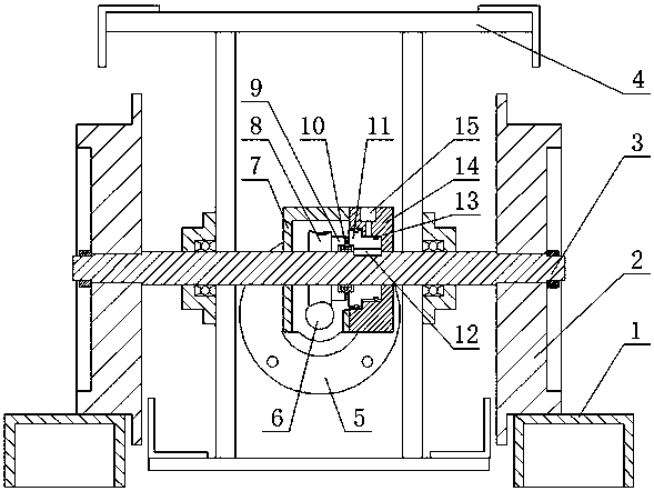
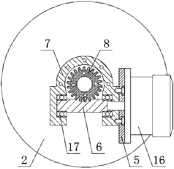
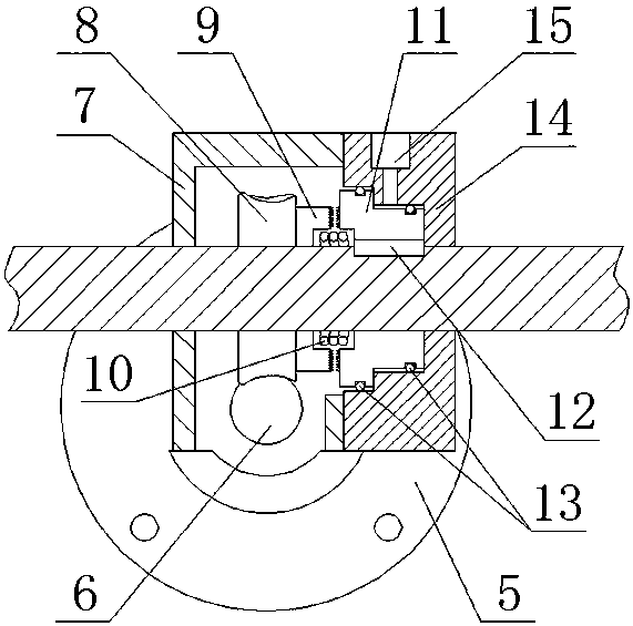
[0019] A pneumatic clutch transmission device for a truss crane trolley, the truss crane trolley includes a vehicle frame 4, a wheel shaft 3 and a wheel 2 for traveling along a track 1, a motor 16 is installed on the vehicle frame 4, A flange 5 is installed on the motor 16, and the end of the flange 5 towards the motor 16 is provided with a plurality of stepped holes capable of accommodating bolt heads. The flange 5 is connected with one end of a housing 7 by bolts, and the motor 16 The output end of the worm shaft 6 is connected with a worm shaft 6. The worm shaft 6 is passed through the housing 7 and supported by a bearing 17. The wheel shaft 3 is provided with a worm wheel 8 meshed with the worm shaft 6. The wheel shaft 3 There is also an active face gear 9 and a passive end face gear 11 set thereon, the active end face gear 9 is connected to the worm wheel 8 so that the active end f...


PUM


Abstract

The invention discloses a pneumatic clutch transmission device for a truss crane pipe car. A motor is mounted on a frame, and is connected with a worm rod shaft; a worm wheel, a driving end surface gear, a driven end surface gear and an end cover sleeve a wheel shaft; the end cover is fixedly connected with the motor through a shell; the driving end surface gear is connected with the worm wheel; aslide shaft key is mounted between the driven end surface gear and the wheel shaft; two sections of peripheral surfaces are arranged on the driven end surface gear; sealing rings sleeve the two sections of peripheral surfaces; two sections of inner circular surfaces on the inner wall of the end cover are pressed on the two sealing rings; the driven end surface gear is ejected to the end surface through a spring, so that a shaft shoulder of the driven end surface gear is bonded with the end surface of the inner wall of the end cover; an air inlet is formed in the end cover, so that air is blown into a gap between the shaft shoulder of the driven end surface gear and the sealing ring on the peripheral surface on one side of the shaft shoulder, the driven end surface gear slides to the driving end surface gear for engagement; and through elastic acting force of the spring, the driven end surface gear is returned after the air is stopped entering the air inlet.

Description

technical field [0001] The invention relates to the field of truss crane trolleys for loading petrochemical oil products, in particular to a pneumatic clutch transmission device for truss crane trolleys. Background technique [0002] The crane tube is the pipeline equipment in the process of fluid loading and unloading in the petrochemical industry. It is used for liquid loading and unloading in the fields of petroleum and chemical industry. A cylinder is installed in the tube trolley, and the cylinder drives the rack to move, and the rack and gear drive to drive the wheels to rotate, so that the trolley can walk on the track, thereby driving the crane tube to move so that the nozzle of the crane tube is docked with the oil port on the railway tank car , in order to realize the loading and unloading of oil products to the railway tank car, the transmission mode of the cylinder and the rack and pinion is simple in structure, small in size and easy to install, and low in cost;...

Claims


Application Information

Patent Timeline
Patent Type & Authority Applications(China)
IPC IPC(8): F16H1/20B61D15/00
CPCF16H1/20B61D15/00
Inventor 井露张长轩杨晖席鲜静郭建强李亮亮丁亮亮
Owner LUOYANG XINPU PETROCHEM EQUIP
Learn More