A System Using Circulators to Realize Optical Fiber Coding

A circulator and optical circulator technology, applied in the testing of machine/structural components, testing optical fiber/optical waveguide equipment, instruments, etc., can solve the problems of inability to uniquely identify, limited identification wavelength, etc., to save costs and improve identification accuracy Effect

Active Publication Date: 2020-12-29
ZHONGSHAN SHUIMU GUANGHUA ELECTRONICS INFORMATION TECH CO LTD
View PDF5 Cites 0 Cited by
  • Summary
  • Abstract
  • Description
  • Claims
  • Application Information

AI Technical Summary

Problems solved by technology

[0002] Optical fiber technology is widely used in the fields of communication, monitoring and control. However, due to the unrecognizability of optical communication, the intelligence in the field of optical fiber technology relies on the unique identification after converting optical signals into electrical signals. The wavelength is limited, and unique identification cannot be realized in a large area. For this reason, a method that not only realizes normal transmission of optical signals but also unique identification is needed

Method used


Image

  • A System Using Circulators to Realize Optical Fiber Coding
  • A System Using Circulators to Realize Optical Fiber Coding
  • A System Using Circulators to Realize Optical Fiber Coding

Examples


Embodiment 1

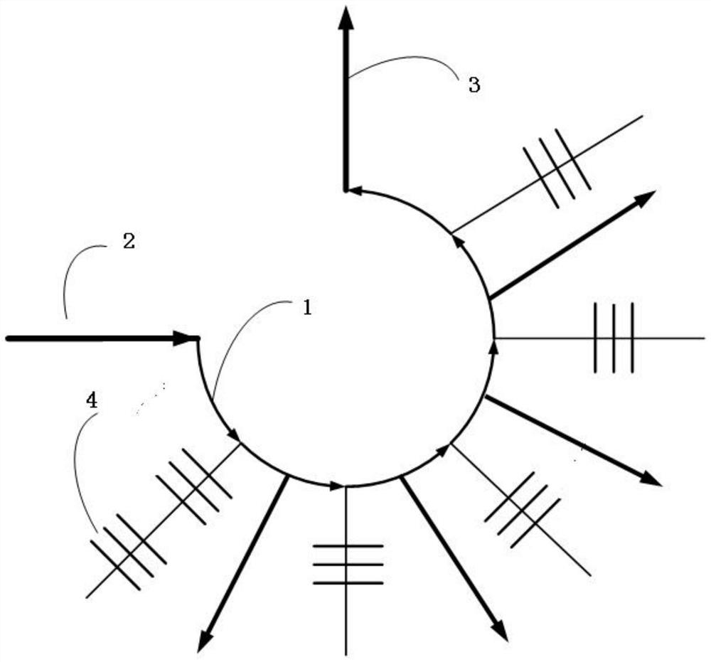
[0026] Such as figure 1 As shown, in a specific embodiment, a system using a circulator to realize optical fiber encoding, the system includes an optical circulator, an input and output end, another input and output end, and a fiber grating;

[0027] The one input and output end, the other input and output end, and the fiber grating are distributed and connected to the optical circulator.

[0028] Fiber gratings are engraved in the branches of the optical circulator;

[0029] Each branch can replicate one or more fiber gratings with different wavelengths.

[0030] The number of fiber gratings replicated in each branch of the optical circulator is unlimited.

[0031] Each fiber grating wavelength in all the branches is used as the coding unit of the fiber code, and the combination of each fiber grating wavelength in all the branches is the code of the fiber code.

[0032] The optical circulator distributes at least one input and output terminal and at least another input and...

Embodiment 2

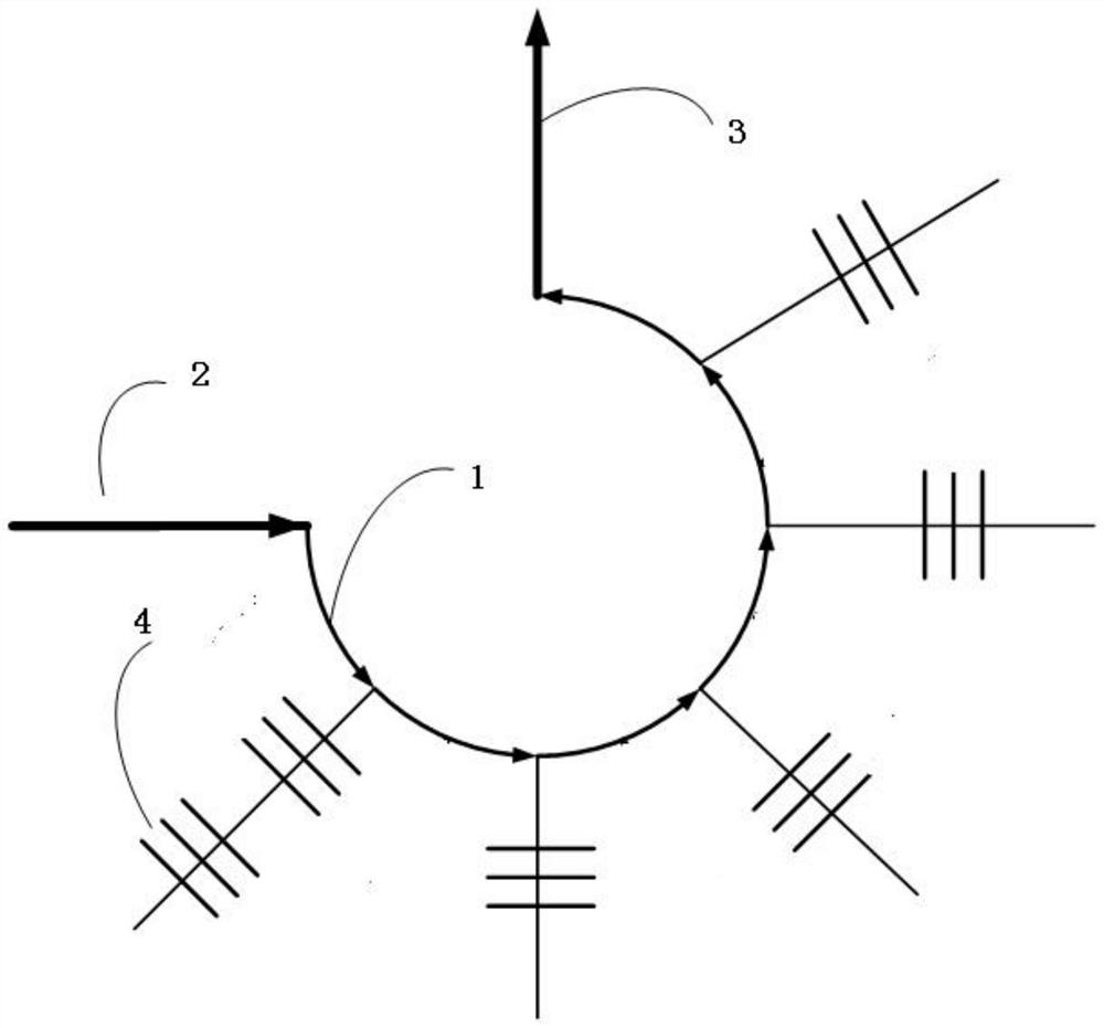
[0040] Such as figure 2 As shown, in a specific embodiment, a system using a circulator to realize optical fiber encoding, the system includes an optical circulator, an input and output end, another input and output end, and a fiber grating;

[0041] The one input and output end, the other input and output end, and the fiber grating are distributed and connected to the optical circulator.

[0042] Fiber gratings are engraved in the branches of the optical circulator;

[0043] Each branch can replicate one or more fiber gratings with different wavelengths.

[0044] The number of fiber gratings replicated in each branch of the optical circulator is unlimited.

[0045] Each fiber grating wavelength in all the branches is used as the coding unit of the fiber code, and the combination of each fiber grating wavelength in all the branches is the code of the fiber code.

[0046] The light enters the circulator from one input and output end, and the fiber gratings in each branch in...

Embodiment 3

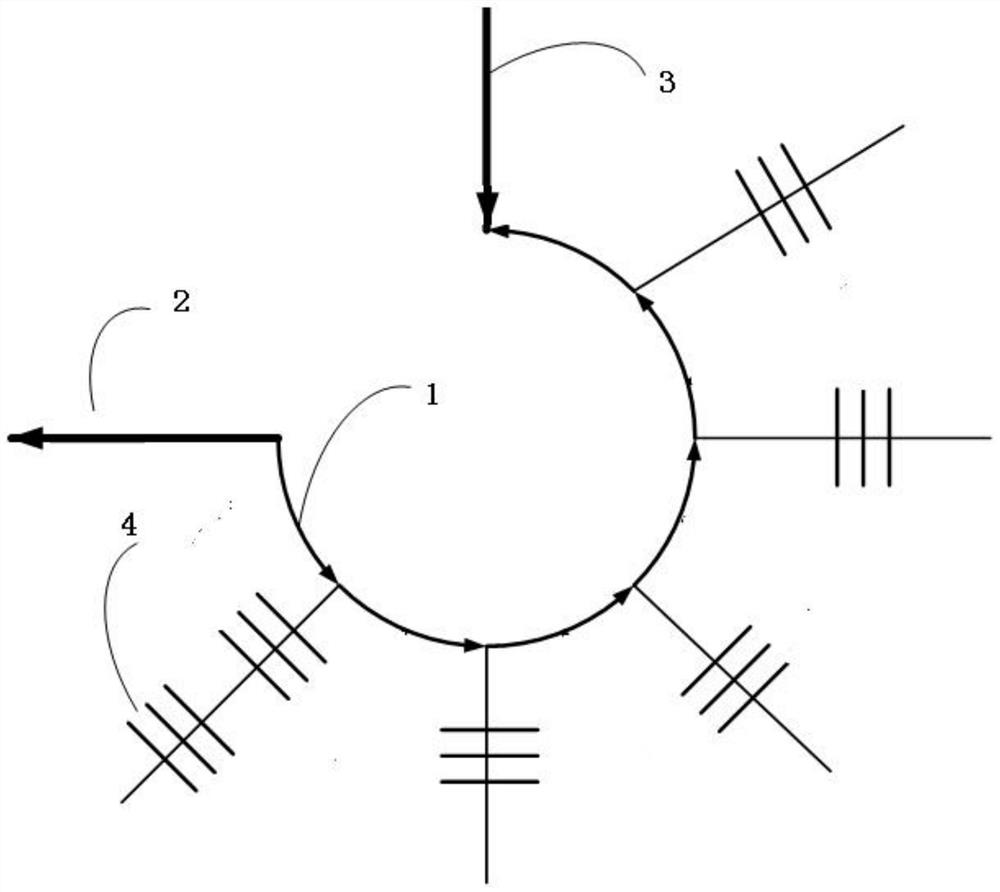
[0054] Such as image 3 As shown, in a specific embodiment, a system using a circulator to realize optical fiber encoding, the system includes an optical circulator, an input and output end, another input and output end, and a fiber grating;

[0055]The one input and output end, the other input and output end, and the fiber grating are distributed and connected to the optical circulator.

[0056] Fiber gratings are engraved in the branches of the optical circulator;

[0057] Each branch can replicate one or more fiber gratings with different wavelengths.

[0058] The number of fiber gratings replicated in each branch of the optical circulator is unlimited.

[0059] Each fiber grating wavelength in all the branches is used as the coding unit of the fiber code, and the combination of each fiber grating wavelength in all the branches is the code of the fiber code.

[0060] The light enters the circulator from one input and output end, and the fiber gratings in each branch in t...


PUM

PropertyMeasurementUnit
wavelengthaaaaaaaaaa

Abstract

The invention provides a system for realizing optical fiber coding by utilizing a circulator. The system comprises at least one optical circulator, an input / output end, another input / output end and fiber Bragg gratings. Optical fiber coding of the optical fiber medium part is realized by re-carving a plurality of fiber Bragg gratings of different wavelengths on circulator branches. With the adoption of the circulator structure, influence on optical cable communication is avoided, and the system is simple in structure, low in cost and excellent in application effect.

Description

technical field [0001] The invention relates to a uniquely identifiable optical fiber grating encoding group method, which belongs to the technical field of unique identification of optical fiber equipment, and can realize unique identification of optical fibers, optical fiber jumpers, optical instruments, and optical communication equipment. Background technique [0002] Optical fiber technology is widely used in the fields of communication, monitoring and control. However, due to the unrecognizability of optical communication, the intelligence in the field of optical fiber technology relies on the unique identification after converting optical signals into electrical signals. The wavelength is limited, and unique identification cannot be realized in a large area. For this reason, a method that not only realizes the normal transmission of optical signals but also realizes unique identification is needed. [0003] Based on the above-mentioned problems existing in the prior a...

Claims


Application Information

Patent Timeline
Patent Type & Authority Patents(China)
IPC IPC(8): G01M11/00
CPCG01M11/00G01M11/31
Inventor 薛鹏朱惠君
Owner ZHONGSHAN SHUIMU GUANGHUA ELECTRONICS INFORMATION TECH CO LTD
Why Eureka
Try Eureka