Check patentability & draft patents in minutes with Patsnap Eureka AI!

A method of image stitching

An image stitching and image technology, applied in the field of image processing, can solve problems such as system crash, memory explosion, and data cannot determine the actual location, and achieve the effect of stable operation and small memory space

Active Publication Date: 2021-10-22
KONFOONG BIOTECH INT
View PDF10 Cites 0 Cited by
  • Summary
  • Abstract
  • Description
  • Claims
  • Application Information

AI Technical Summary

Problems solved by technology

[0005] like figure 2 As shown, one of the areas of the pathological section is selected for scanning. There are tissues in the edge part and a blank part in the middle. If the area array camera captures a picture in the blank area, the captured picture will be a white picture. If the actual offset cannot be calculated, the image of this block cannot determine the actual position, so that the data behind this block cannot determine the actual position
In fact, the tissue part at the bottom of the center can be determined by splicing the tissue on the right side, so the data at the bottom of the center needs to be determined by reverse reasoning when scanning to the last column, but this leads to another problem, the middle contains blank areas The image data of a column must wait until the last column is scanned before the data can be released. This will cause the memory data to not be released in time. When a column of data is relatively large, the memory will explode, causing the system to crash

Method used


Image

  • A method of image stitching
  • A method of image stitching
  • A method of image stitching

Examples


Embodiment Construction

[0027] The present invention will be further described below in conjunction with the accompanying drawings and embodiments.

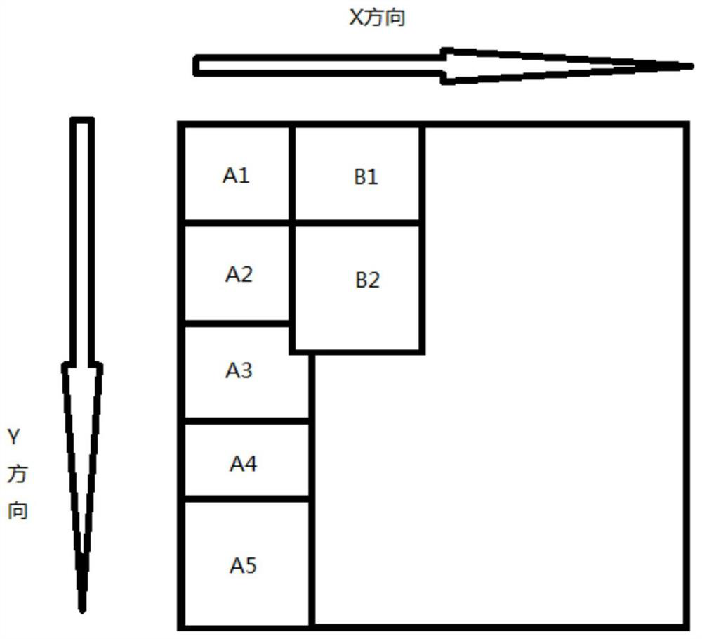
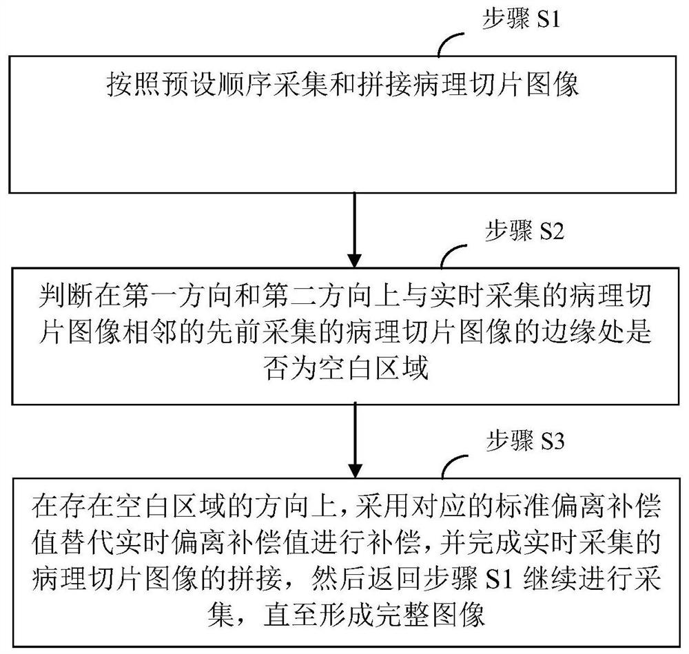
[0028] In a preferred embodiment, as image 3 As shown, an image stitching method is proposed, which is applied to a digital pathological scanner that uses an area array camera to collect images. The digital pathological scanner overlaps at the edges of a first direction and a second direction according to a preset order The pathological slice images are spliced ​​to form a complete image, and each pathological slice image is offset compensated according to the real-time offset compensation value detected in real time;

[0029] Wherein, the mobile platform of the digital pathological scanner is driven by a servo motor; the digital pathological scanner pre-stores the first-type standard deviation compensation value about the first direction, and pre-stores the second-type standard deviation compensation value about the second direction;

[0030] Image s...


PUM


Abstract

The present invention relates to an image processing technology, in particular to an image splicing method. The mobile platform of a digital pathological scanner is driven by a servo motor; it includes: step S1, collecting and splicing pathological slice images according to a preset sequence; step S2, judging the Whether there is a blank area at the edge of the previously acquired pathological slice image adjacent to the currently acquired pathological slice image in the first direction and the second direction; if there is a blank area in at least one direction, then turn to step S3; If there is no blank area in the first direction and the second direction, then return to step S1 to continue collecting; step S3, in the direction where there is a blank area, use the corresponding standard deviation compensation value instead of the real-time deviation compensation value for compensation, and complete the current The splicing of the collected pathological slice images, and then return to step S1 to continue collecting until a complete image is formed; the occupied memory space is small, the operation is stable, and the system crash caused by insufficient memory will not occur.

Description

technical field [0001] The invention relates to an image processing technology, in particular to an image splicing method. Background technique [0002] The digital pathology scanner is mainly composed of a mobile platform, a preview camera, an area array camera, a light source, an objective lens, related sensors, and a control board. By controlling the movement of the platform and synchronously controlling the area array camera to take pictures, each image There are overlapping parts between them, and the broken pictures taken are uploaded to the computer and recognized, and spliced ​​into a large picture. [0003] Such as figure 1 As shown, the area array camera will first capture the A1-A5 data map, and then take the B column data map. There is a default overlap height compensation between A1 and A2 in the Y direction, and a default overlap width in the X direction between A1 and B1. Compensation, using these coincident images to calculate the degree of coincidence. ...

Claims


Application Information

Patent Timeline
Patent Type & Authority Patents(China)
IPC IPC(8): G06T3/40
CPCG06T3/4038
Inventor 刘炳宪谢菊元王焱辉王克惠胡幸超
Owner KONFOONG BIOTECH INT
Features
  • R&D
  • Intellectual Property
  • Life Sciences
  • Materials
  • Tech Scout
  • Unparalleled Data Quality
  • Higher Quality Content
  • 60% Fewer Hallucinations
Learn More