

Image splicing method and device
A technology for splicing images and images, applied in the field of image processing, can solve the problems of high algorithm complexity, low image processor configuration, slow image splicing speed, etc. Process fast and efficient results
- Summary
- Abstract
- Description
- Claims
- Application Information
AI Technical Summary
Problems solved by technology
Method used
Image

Examples
Embodiment 1
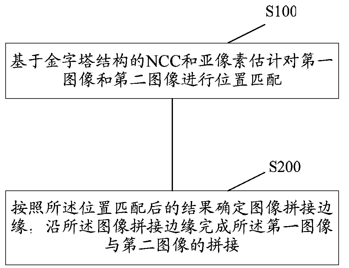
[0076] Such as figure 1 As shown, it is a schematic flow chart of the method for splicing images according to Embodiment 1 of the present invention, including:
[0077] Step S100: Perform position matching on the first image and the second image based on the normalized cross correlation coefficient (NCC, Normalized Cross Correlation) of the pyramid structure and sub-pixel estimation. Wherein, the first image and the second image are two adjacent images to be spliced. Those skilled in the art know that adjacent images to be spliced refer to two images that can be spliced with overlapping regions. Taking a mobile phone with a camera function as an example, when the user turns on the panorama shooting function, the mobile phone will automatically generate multiple successively adjacent captured images according to the movement of the shooting angle, that is, the images to be stitched. The image stitching method provided in this embodiment can be used to stitch any two adjac...
Embodiment 2
[0101] The method for stitching images provided in this embodiment is a method for stitching panoramic images, such as Figure 6 shown, including:
[0102] Step S21: Acquiring adjacent images in sequence. For example, when a user takes a panoramic shot, the images are generated sequentially. As mentioned above, the user presses the shutter to get the first image, and then when the translation position of the captured image reaches the system setting, it will shoot to get the second image, and so on, to get the last image in turn, Therefore, these images are sequentially adjacent to each other according to the shooting sequence.
[0103] Step S22: matching the second image with the first image, determining the image stitching edge, and completing the stitching. In this embodiment, the first image specifically refers to the first image acquired or the image after splicing is completed, for example, the image that has been spliced is the image spliced from the first image ...
Embodiment 3
[0108] The method for stitching images provided in this embodiment is another method for stitching panoramic images, such as Figure 7 shown, including:
[0109] Step S31: Obtain a series of sequentially adjacent images.
[0110] Step S32: Determine the image mosaic edges of all adjacent images. For the specific determination process, reference may be made to the relevant steps in Embodiment 1.
[0111] Step S33: Stitching all the images together to form a panoramic image.
[0112] The method for stitching panoramic images provided in this embodiment has high stitching efficiency, fast speed, and high stitching accuracy. Different from Embodiment 2, this embodiment does not limit the order of splicing, and splicing can be performed sequentially according to the sequence of images, or multiple images can be spliced at the same time when the image processing capability is strong, so as to adapt to more applications Scenes.
PUM
 Abstract
Description
Claims
Application Information