Electromagnetic trigger
A technology of electromagnetic trigger and magnet, applied in the direction of electrical components, electromechanical devices, etc.
Inactive Publication Date: 2018-09-14
苏州波斯特克精密电机有限公司
View PDF4 Cites 0 Cited by
- Summary
- Abstract
- Description
- Claims
- Application Information
AI Technical Summary
Problems solved by technology
However, there is no electromagnetic trigger that makes the trigger movement direction consistent with the magnetization direction of the magnet.
Method used
View moreImage
Smart ImageViewing Examples


Examples
Embodiment
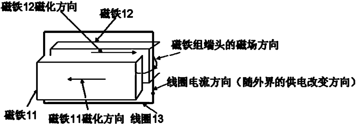
[0010] An electromagnetic trigger, comprising a coil 13, a first magnet 11 and a second magnet 12, the first magnet 11 and the second magnet 12 are placed side by side, and the magnetization directions of the two magnets are opposite; the coil 13 is placed on the two magnets Between and the two ends of the coil 13 are located at the two ends of the magnet; the direction of the current in the coil 13 is variable.
Login to View More PUM
 Abstract
The invention discloses an electromagnetic trigger. The electromagnetic trigger comprises a coil, a first magnet and a second magnet, wherein the first magnet and the second magnet are arranged side by side; the magnetization directions of the two magnets are opposite to each other; the coil is arranged between the two magnets; the two ends of the coil are positioned at the two ends of the magnets; and the current direction in the coil is variable. The electromagnetic trigger can achieve the purpose that the motion direction of the trigger and the magnetization directions of the magnets are the same through only two magnets, and realizes the side-to-side movement of the coil.
Description
technical field [0001] The present invention relates to an electromagnetic trigger. Background technique [0002] Electromagnetic triggers are used in many fields. The physical principle is that the current-carrying conductor will move under force in the magnetic field generated by the permanent magnet. One of the typical applications is the swing, as Figure 1 shown. Magnet assembly 1 is made up of magnet 1 and 2, and the magnetization direction of magnet 1 and 2 is perpendicular to the plane and the magnetization direction is opposite. The magnet assembly II is composed of magnets 3 and 4. The magnetization directions of magnets 3 and 4 are perpendicular to the plane and opposite to each other, but the magnetization directions of 3 and 1 are the same, and the magnetization directions of 4 and 2 are the same. Assemble components I and II with 3 pairs of 1, 4 pairs of 2, face to face and a certain distance apart to form a complete component. Between magnet 3 and 1 like th...
Claims
Login to View More Application Information
Patent Timeline
 IPC IPC(8): H02K33/18
CPCH02K33/18
Inventor 候春涛
Owner 苏州波斯特克精密电机有限公司

PatSnap Eureka turns technology decisions into work you can execute. Powered by our Innovation Knowledge Graph, it runs expert workflows across engineering, life sciences, materials and intellectual property. Get your review-ready output in minutes.


