Medical mask smashing garbage can
A technology of trash cans and masks, applied in the field of trash cans, can solve the problems of a large amount of time consumption, late disinfection time, easy spread of germs, etc., and achieve the effect of reducing manual operations, narrowing gaps, and reducing the spread of germs
- Summary
- Abstract
- Description
- Claims
- Application Information
AI Technical Summary
Problems solved by technology
Method used
Image
Examples
Embodiment 1
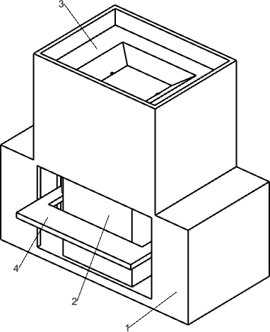
[0041] A medical mask broken trash can such as figure 1 As shown, it includes an outer shell 1, an inner shell 2, a square funnel 3, a shredding mechanism 4 and a disinfection mechanism 5. The inner shell 2 is installed inside the outer shell 1, and the top of the inner shell 2 is provided with a square funnel 3. The inside and outside of the inner shell 2 are equipped with Shredding mechanism 4 is arranged, and disinfection mechanism 5 is installed on the right side and the front side of inner shell 2, and disinfection mechanism 5 is connected with tearing mechanism 4.
[0042] When the used medical mask needs to be thrown away, the medical mask is first thrown into the inner shell 2 from the square funnel 3 manually, the collection box is placed on the lower right side of the inner shell 2, and then the shredding mechanism 4 is stepped down The parts of the shredding mechanism 4 will run to shred the medical mask. At the same time, manually stepping on the parts of the shred...
Embodiment 2
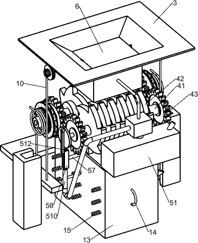
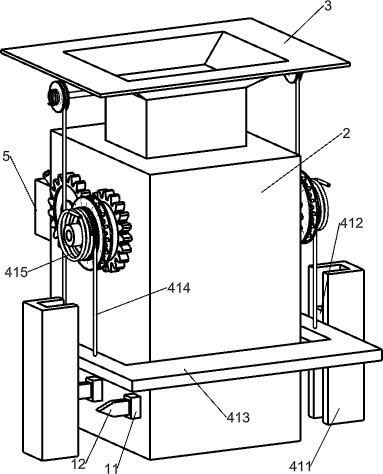
[0044] Specifically, such as Figure 2-5 As shown, the shredding mechanism 4 includes a transmission shaft 41, a cutter 42, a gear 43, a toothed disc 44, a sliding disc 45, a block 46, a connecting shaft 47, a sector block 48, a first elastic member 49, a winding ring 410, First slide rail 411, square slide block 412, pedal 413, stay cord 414 and second elastic member 415, two transmission shafts 41 are arranged in rotation between the front and back inner walls of the inner shell 2 top, and the transmission shaft 41 is provided with cutters 42. Gears 43 are connected to the front and rear sides of the transmission shaft 41, and the two adjacent gears 43 are meshed. The gears 43 are located outside the inner shell 2. The front and rear sides of the left transmission shaft 41 are equipped with toothed discs 44. 43 is located between the toothed discs 44, and the front and rear sides of the toothed discs 44 are slidingly provided with a sliding plate 45, and a connecting shaft 4...
Embodiment 3
[0049] according to Figure 2-3 and Figure 6 As shown, it also includes a rotating plate 6, a rotating shaft 7, a reel 8, a third elastic member 9 and a rope 10, and a rotating shaft 7 is rotated between the front and rear walls of the upper part of the casing 1, and a rotating plate 6 is installed in the middle of the rotating shaft 7. , the front and rear sides of the rotating shaft 7 are provided with a reel 8, a third elastic member 9 is connected between the side of the reel 8 and the inner wall of the housing 1, a rope 10 is wound around the reel 8, and the end of the rope 10 is connected to a pedal 413 top.
[0050] Manually place the collection box on the lower right side of the inner shell 2, step on the pedal 413, the pedal 413 drives the rope 10 to pull down, the rope 10 drives the winding wheel 8 to rotate, the third elastic member 9 is compressed, and the winding wheel 8 drives the rotating shaft 7 to rotate , the rotating shaft 7 rotates to drive the rotating ...
PUM
 Abstract
Description
Claims
Application Information
 - R&D
- Intellectual Property
- Life Sciences
- Materials
- Tech Scout
- Unparalleled Data Quality
- Higher Quality Content
- 60% Fewer Hallucinations
Browse by: Latest US Patents, China's latest patents, Technical Efficacy Thesaurus, Application Domain, Technology Topic, Popular Technical Reports.
© 2025 PatSnap. All rights reserved.Legal|Privacy policy|Modern Slavery Act Transparency Statement|Sitemap|About US| Contact US: help@patsnap.com


