
Film wrapping device for automatic storage

A warehousing and wrapping technology, which is applied in the direction of packaging material feeding device, packaging, transportation and packaging, etc., can solve the problems of inability to wrap the container and wrap it, and achieve the effect of improving stability, reducing use limitations and saving manpower.

Inactive Publication Date: 2018-09-18
苏州奇思汇智能科技有限公司
View PDF0 Cites 9 Cited by
  • Summary
  • Abstract
  • Description
  • Claims
  • Application Information

AI Technical Summary

Problems solved by technology

[0002] As we all know, the wrapping machine is also called tray wrapping machine, stretch film wrapping machine, etc., commonly known as tray wrapping machine, is a special packaging machine for mechanized wrapping, and is an indispensable package for modernization, especially for export-oriented enterprises. Machine, wrapping device for automatic storage is an auxiliary device for wrapping stretch film on boxes of goods, so as to better protect the boxes from moisture and rain, and it has been widely used in the field of automatic storage; The existing film wrapping device for automatic storage includes a base plate, a placement plate, a lower rotating shaft, a rear side plate, a support plate and a pillar. A placement groove is arranged on the top of the bottom plate, and upper balls are fixedly installed on the upper side and the lower side of the placement groove. Bearing and lower ball bearing, the bottom end of the lower rotating shaft passes through the interior of the upper ball bearing and the lower ball bearing respectively, and the outer wall of the lower rotating shaft is fixedly connected with the upper ball bearing and the lower ball bearing respectively, and the top end of the lower rotating shaft is connected with the bottom of the placing plate The bottom end of the rear side plate is connected with the top rear side of the bottom plate, the left end of the support plate is connected with the right end of the rear side plate, and the bottom end of the pillar is connected with the top right side of the support plate; When the film device is used, firstly, the box is transported to the placement board by a forklift and a pallet, then the stretch film is inserted on the pillar, stretched out, the stretch film is wrapped on the box, and the lower shaft is rotated to complete the process. Winding is enough; in the use of the existing film wrapping device for automatic storage, it is found that due to the fixed position of the support plate, the size of the box is different. It is impossible to fully wrap the container goods, resulting in high limitations in use; and the stability of the container goods on the placement board is poor, and the manual rotation of the placement board at the same time wastes manpower, resulting in poor reliability in use

Method used


Image

  • Film wrapping device for automatic storage
  • Film wrapping device for automatic storage
  • Film wrapping device for automatic storage

Examples


Embodiment Construction

[0024] The specific implementation manners of the present invention will be further described in detail below in conjunction with the accompanying drawings and embodiments. The following examples are used to illustrate the present invention, but are not intended to limit the scope of the present invention.

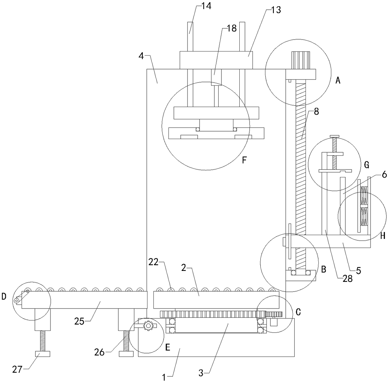
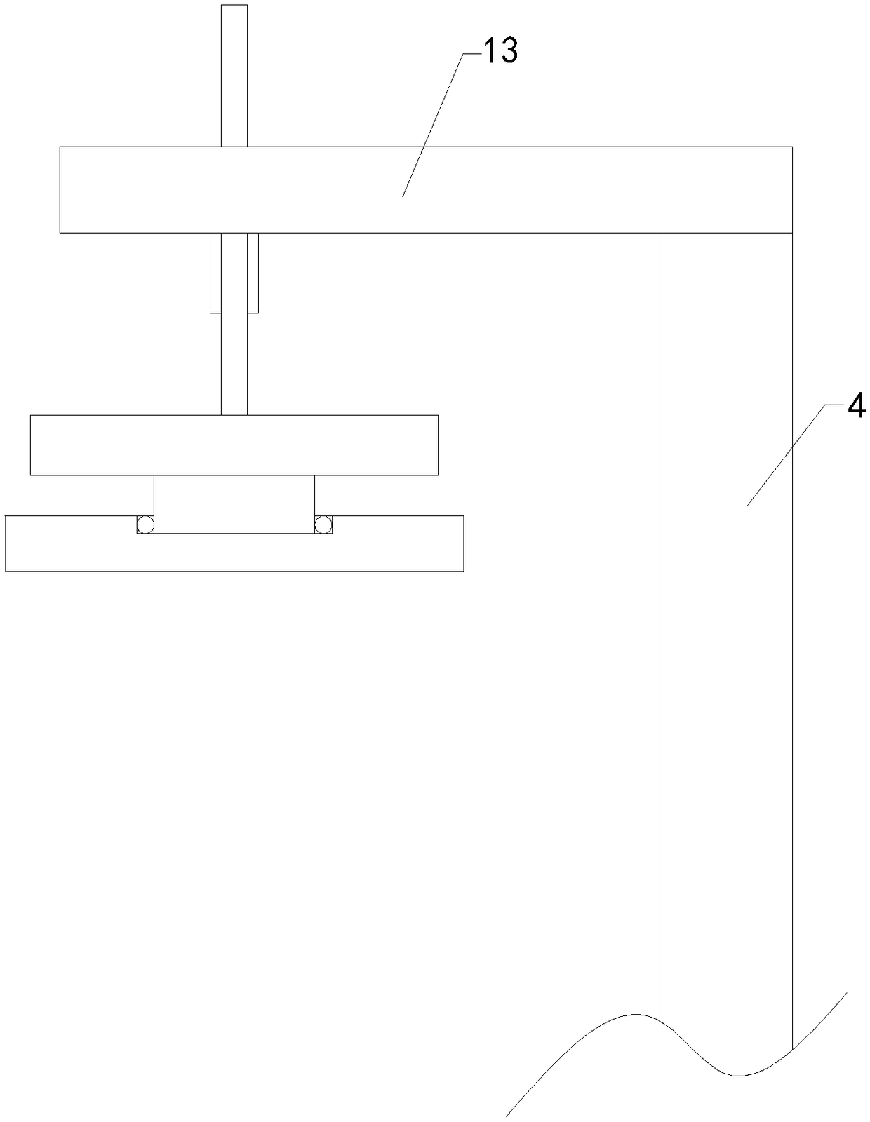
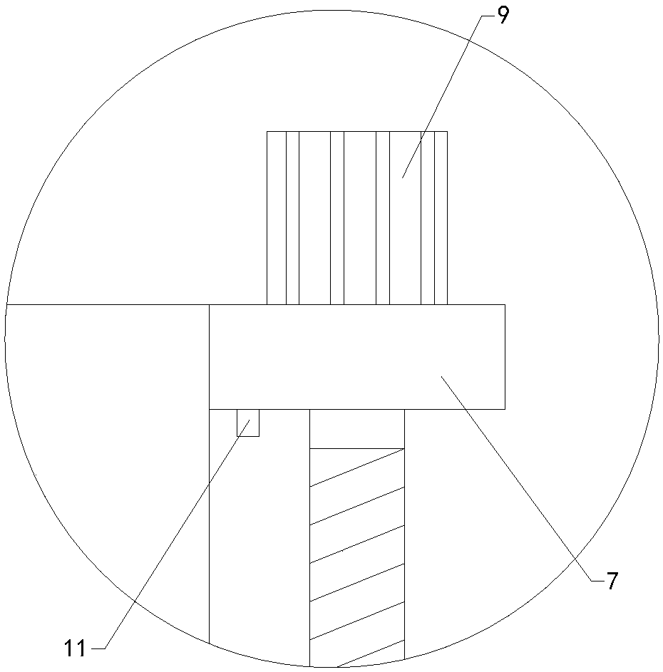
[0025] Such as Figure 1 to Figure 10As shown, a film wrapping device for automatic storage of the present invention includes a base plate 1, a placement plate 2, a lower rotating shaft 3, a rear side plate 4, a support plate 5 and a pillar 6, a placement groove is provided on the top of the bottom plate, and the inside of the placement groove An upper ball bearing and a lower ball bearing are fixedly installed on the upper and lower sides of the upper and lower sides respectively, the bottom ends of the lower rotating shaft pass through the inner parts of the upper ball bearing and the lower ball bearing respectively, and the outer walls of the lower rotating shaft are co...


PUM


Abstract

The invention relates to the technical field of automatic storage accessory devices, in particular to a film wrapping device for automatic storage. A container cargo can be wrapped by stretching filmscomprehensively, and the usage limitation is reduced; the stability of the container cargo on placement plates is improved, and meanwhile the manual rotation of the placement plates is not required;manpower is saved, and the application reliability is improved; the film wrapping device comprises a baseplate, the placement plates, a lower rotating shaft, a rear side plate, a support plate, a support column, an upper fixed plate, a lower fixed plate, regulating lead screws, servo motors, regulating lead screws, a travel switch, an upper touch block and a lower touch block, and further comprises a top plate, two groups of limit rods, a lifting plate, an upper rotating shaft, a pressing plate, an electric telescopic cylinder and a gear motor; the rear side of the bottom end of the top plateis connected to the top end of the rear side plate, and the top end of the electric telescopic cylinder is connected to the middle part of the bottom end of the top plate; and the top end of the lifting plate is connected to the bottom end of a telescopic rod in the electric telescopic cylinder, and the two limit rods are located on the left and right sides of the electric telescopic cylinder separately.

Description

technical field [0001] The invention relates to the technical field of automatic storage attachments, in particular to a film wrapping device for automatic storage. Background technique [0002] As we all know, the wrapping machine is also called tray wrapping machine, stretch film wrapping machine, etc., commonly known as tray wrapping machine, is a special packaging machine for mechanized wrapping, and is an indispensable package for modernization, especially for export-oriented enterprises. Machine, wrapping device for automatic storage is an auxiliary device for wrapping stretch film on boxes of goods, so as to better protect the boxes from moisture and rain, and it has been widely used in the field of automatic storage; The existing film wrapping device for automatic storage includes a base plate, a placement plate, a lower rotating shaft, a rear side plate, a support plate and a pillar. A placement groove is arranged on the top of the bottom plate, and upper balls are ...

Claims


Application Information

Patent Timeline
Patent Type & Authority Applications(China)
IPC IPC(8): B65B11/04B65B41/12
CPCB65B11/045B65B41/12
Inventor 谈有进
Owner 苏州奇思汇智能科技有限公司
Learn More