Yarn breakage retracting device for facilitating broken end connecting

A technology for yarn unwinding and yarn breakage, applied in textiles and papermaking, etc., can solve the problems of no inspection of yarn breakage parts, unfavorable workshop production, affecting normal spindle winding, etc., to facilitate broken ends and to avoid device breakage. The effect of yarn misjudgment and ensuring stable operation

Inactive Publication Date: 2018-09-18
柳州大蘑王网络科技有限公司
View PDF0 Cites 3 Cited by
  • Summary
  • Abstract
  • Description
  • Claims
  • Application Information

AI Technical Summary

Problems solved by technology

[0003] The current spinning frame only has the function of yarn breakage alarm, and does not check the specific breakage of the yarn, so that the workshop personnel cannot continue to connect the broken end of the yarn immediately after the machine breaks. Existing patent There is a quick search for the broken end of the first yarn through the airflow, but this method will make the yarn swing freely, affect the normal winding of other normal spindles, and is not conducive to the production of the workshop, so it is suitable for fast yarn search for spinning frames The device for thread breaking is a technical problem that those skilled in the art need to solve

Method used


Image

  • Yarn breakage retracting device for facilitating broken end connecting
  • Yarn breakage retracting device for facilitating broken end connecting
  • Yarn breakage retracting device for facilitating broken end connecting

Examples


Embodiment Construction

[0030] The following will clearly and completely describe the technical solutions in the embodiments of the present invention with reference to the accompanying drawings in the embodiments of the present invention. Obviously, the described embodiments are only some, not all, embodiments of the present invention. Based on the embodiments of the present invention, all other embodiments obtained by persons of ordinary skill in the art without creative efforts fall within the protection scope of the present invention.

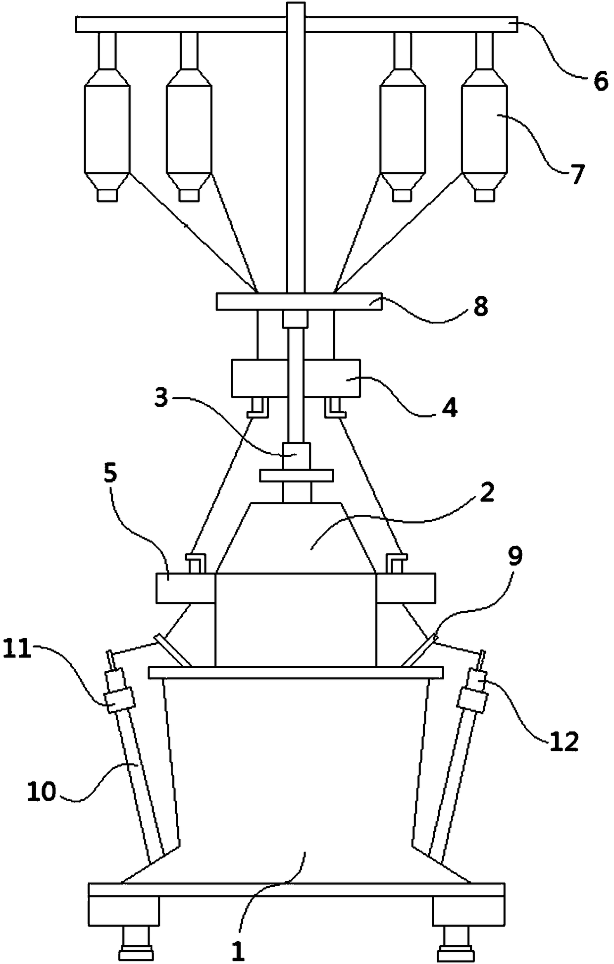
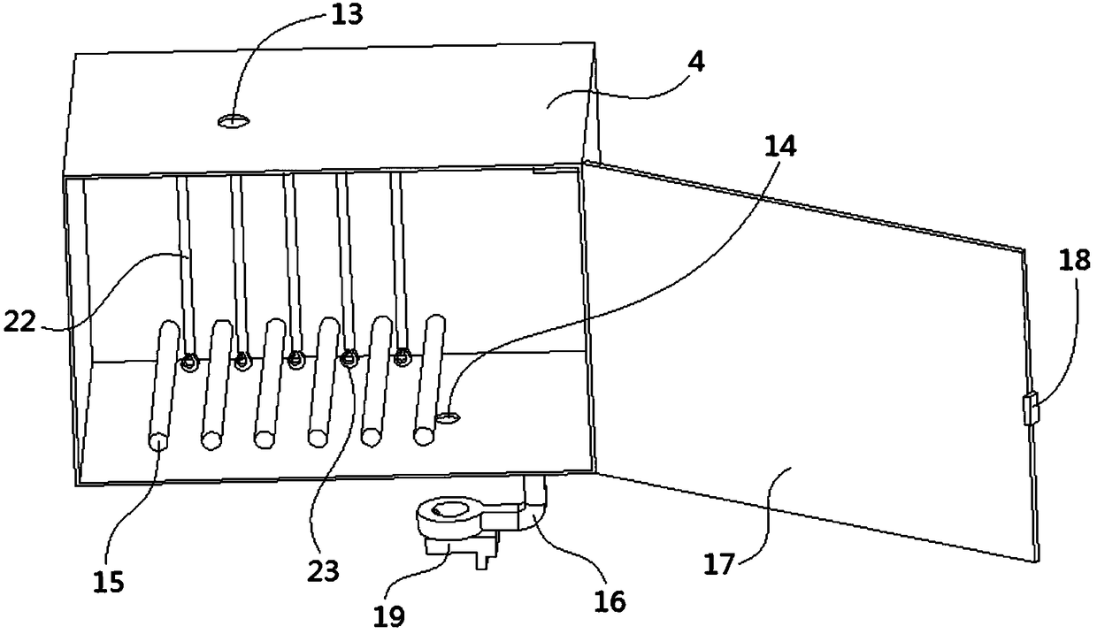
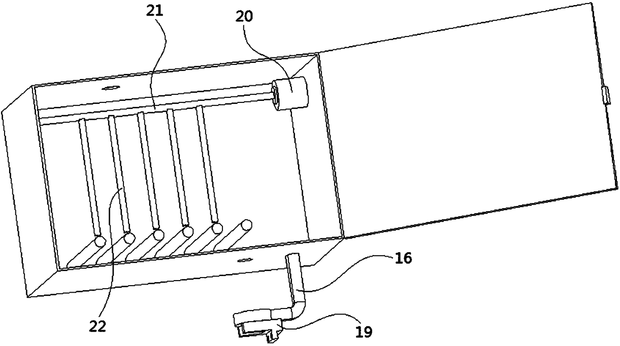
[0031] see Figure 1-3 , the present invention provides a technical solution: a broken yarn unwinding device that is beneficial to broken ends and splicing, including a base 1, a surface of the base 1 is fixedly connected with a fixing seat 2, and a surface of the fixing seat 2 is fixedly connected with a column 3, Both sides of the column 3 are fixedly connected with an upper wire unwinding device 4, and both sides of the fixing base 2 are fixedly connected with a...


PUM


Abstract

The invention discloses a yarn breakage retracting device for facilitatingbroken end connecting, and relates to the technical field of spinning machinery. The device comprises a base, a fixed seat isfixedly connected to the surface of the base, a standing column is fixedly connected to the surface of the fixed seat, upper retracting devices are fixedly connected on both sides of the standing column,lower retracting devicesare fixedly connected on both sides of the fixed seat, the inner surfaces of the upper retracting device and the lower retracting device are fixedly connected with retracting motors, the ends of the output shafts of the retracting motorsare fixedly connected with rotating rods, a plurality of lanyards are fixedly connected to the circumferential side surfaces of the rotating rods, hooksare fixedly connected with the ends of the lanyards, and the inner surfaces of the upper retracting device and the lower retracting device are rotatably connected with a plurality of rolling rods. Through the cooperationof the upper retracting device and the lower retracting device, the length of a fold line inside the device is increased through the hooks, so that a broken end ofa yarn is retracted toward the device, the broken end of the yarn can be quickly found, and the device has the advantage of facilitating the yarn broken end connecting.

Description

technical field [0001] The invention relates to the technical field of spinning machinery, in particular to a broken yarn unwinding device which is beneficial to continuous splicing of broken ends. Background technique [0002] Spinning frame, a spinning machine that draws, twists, and winds semi-finished roving or sliver into spun bobbins during the spinning process. The output and quality of spun yarn are a comprehensive reflection of the pros and cons of each process in the spinning process. The production unit of the spinning machine is the spindle, and the production level of the spinning frame is often measured by the output per thousand spindle hours. The production scale of the spinning mill is expressed by the total number of spindles owned by the spinning frame. The yarn spun on each spindle will be broken due to various reasons, and the broken end rate is often expressed by the number of broken ends that occur in 1,000 spindle hours. The level of broken ends aff...

Claims


Application Information

Patent Timeline
Patent Type & Authority Applications(China)
IPC IPC(8): D01H13/16
CPCD01H13/1633
Inventor 杨继华李振聪
Owner 柳州大蘑王网络科技有限公司
Why Eureka
Try Eureka